
Special-shaped group hole machining system and machining method

A processing system and processing method technology, applied in the direction of metal processing equipment, manufacturing tools, process efficiency improvement, etc., can solve the problems of large thermal response on the surface of small holes, difficult taper control, thick remelting layer on the hole wall, etc., to achieve motion Fast speed, reduced spot overlap, and fast adjustment speed

Pending Publication Date: 2022-08-02
江苏先河激光技术有限公司 +1
View PDF9 Cites 0 Cited by
  • Summary
  • Abstract
  • Description
  • Claims
  • Application Information

AI Technical Summary

Problems solved by technology

At this stage, the drilling method of special-shaped holes is mainly used in the form of galvanometer scanning, but this drilling method has the problems of difficult control of taper, large thermal reaction on the surface of small holes, and thick remelted layer on the hole wall.

Method used


Image

  • Special-shaped group hole machining system and machining method
  • Special-shaped group hole machining system and machining method
  • Special-shaped group hole machining system and machining method

Examples


Embodiment Construction

[0031] The technical solutions in the embodiments of the present invention will be clearly and completely described below with reference to the accompanying drawings in the embodiments of the present invention. Obviously, the described embodiments are only a part of the embodiments of the present invention, but not all of the embodiments. Based on the embodiments of the present invention, all other embodiments obtained by those of ordinary skill in the art without creative efforts shall fall within the protection scope of the present invention.

[0032] In the description of the present invention, it should be understood that the terms "center", "upper", "lower", "front", "rear", "left", "right", "vertical", "horizontal", The orientation or positional relationship indicated by "top", "bottom", "inner", "outer", etc. is based on the orientation or positional relationship shown in the drawings, and is only for the convenience of describing the present invention and simplifying th...


PUM


Abstract

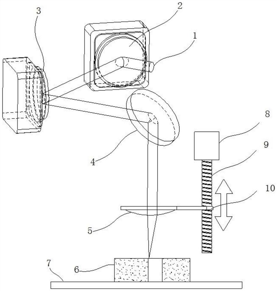
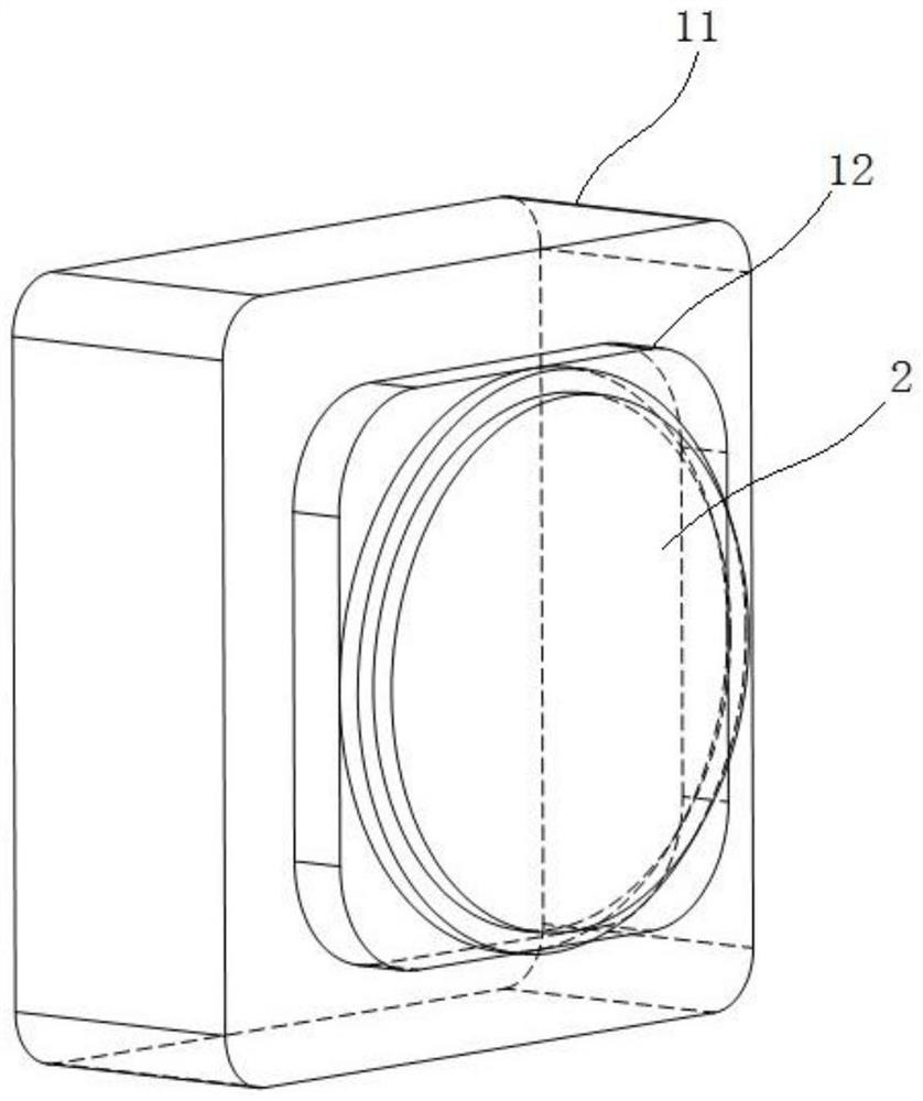
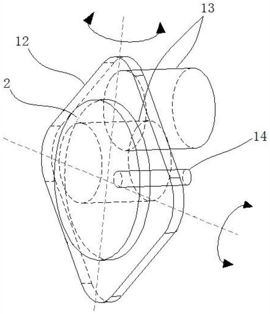
The invention provides a special-shaped group hole machining system which comprises a machining platform, a laser device, an offset and deflection adjusting unit and a focusing motion unit, the offset and deflection adjusting unit and the focusing motion unit are sequentially arranged between the laser device and the machining platform along a laser light path, and the offset and deflection adjusting unit comprises a first two-dimensional reflector and a second two-dimensional reflector which are mutually compensated and controlled in a linkage mode. The first deflection adjusting mechanism and the second deflection adjusting mechanism respectively control the two-dimensional reflecting mirror I and the two-dimensional reflecting mirror II to rotate in a two-dimensional range, and the focusing motion unit comprises a reflecting mirror, a telecentric focusing mirror and a focusing assembly. According to the invention, the position of the incident dynamic laser beam is adjusted through the combined action of the offset and deflection adjustment of the offset and deflection adjustment unit on the laser beam and the adjustment of the focus position in the small hole machining process by the focusing motion unit, the adjustment speed is high, the error caused in the adjustment process is small, and the adjustment precision is high. The laser beam can be accurately hit to a pre-machining position, the time for adjusting the position after one small hole is hit is shortened, and efficiency is improved.

Description

technical field [0001] The invention belongs to the technical field of laser processing, and particularly relates to a special-shaped group hole processing system and a processing method. Background technique [0002] Micro holes have a wide range of applications in the industrial field, especially the demand for small micro deep holes is increasing. The aerospace industry, automotive engine, and chip manufacturing industry all have a large number of various sizes and various tapers and various The shape of the small hole also has high requirements on the precision of the small hole and the repeatability of the small hole processing. At this stage, the most commonly used special-shaped hole punching method is mainly the form of galvanometer scanning, but this kind of punching method has the problems of difficult taper control, large thermal reaction on the surface of the small hole, and thick remelting layer on the hole wall. SUMMARY OF THE INVENTION [0003] The purpose ...

Claims


Application Information

Patent Timeline
Patent Type & Authority Applications(China)
IPC IPC(8): B23K26/384B23K26/082B23K26/064B23K26/70
CPCB23K26/384B23K26/082B23K26/0643B23K26/702Y02P40/57
Inventor 秦应雄秦庆全龙宙段光前黄树平童杰
Owner 江苏先河激光技术有限公司
Learn More