
Fuel cell anode circulation system and control method thereof

A circulation system and fuel cell technology, applied in fuel cells, circuits, electrical components, etc., can solve the problems of limited reflux capacity and inability to adjust the idling point of the ejector, and achieve increased concentration, simple regulation and flexible control methods Effect

Pending Publication Date: 2022-07-29
BEIJING SINOHYTEC
View PDF0 Cites 0 Cited by
  • Summary
  • Abstract
  • Description
  • Claims
  • Application Information

AI Technical Summary

Problems solved by technology

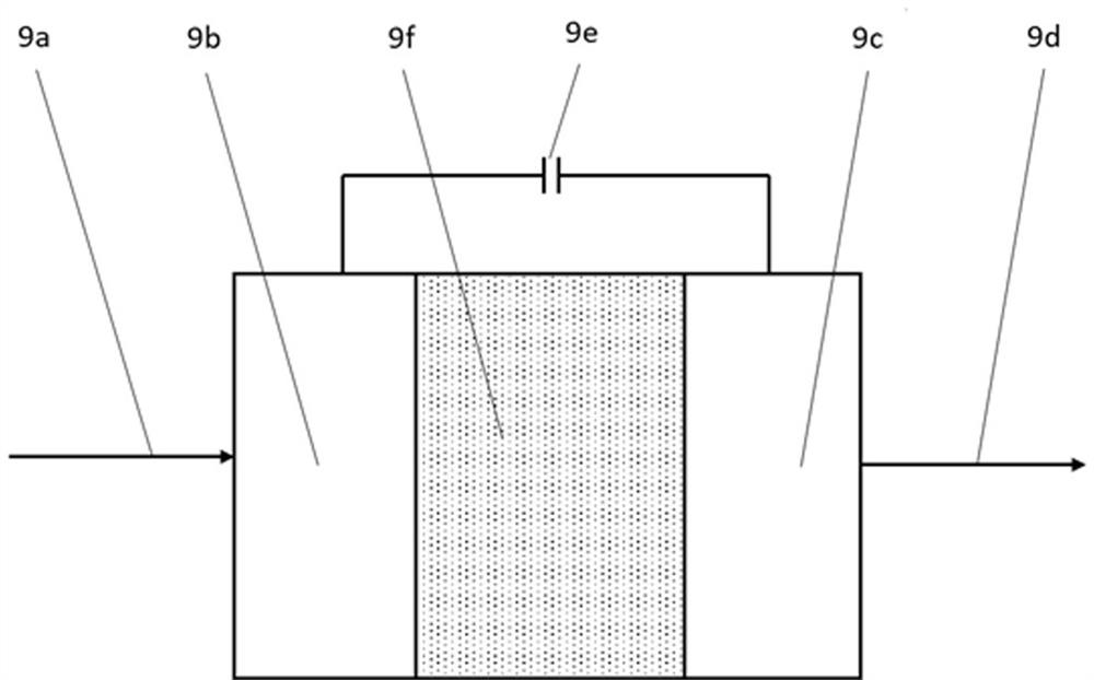
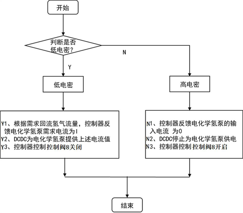
[0005] Aiming at the problem that the reflux capacity of the idle point of the ejector in the prior art is limited and cannot be adjusted, the present invention provides a fuel cell anode circulation system, including: a hydrogen tank, a stack, an ejector, a water separator, an electrochemical Hydrogen pump, controller, DCDC; the inlet of the ejector is connected to the hydrogen tank, and the outlet of the ejector is connected to the anode inlet of the stack to form an air intake path; the return port of the ejector is connected to the outlet of the water separator The air port is connected, and a control valve is set between the ejector return port and the water separator, and the water separator air inlet is connected with the anode outlet of the stack to form a hydrogen circulation path; the outlet of the electrochemical hydrogen pump It is connected with the anode inlet of the electric stack, and the inlet of the electrochemical hydrogen pump is connected with the anode outlet of the electric stack; the controller is used to control the work of the ejector and / or the electrochemical hydrogen pump according to the current working conditions; the The DCDC described above is used to convert the current of the stack into the current required by the controller and the electrochemical hydrogen pump

Method used


Image

  • Fuel cell anode circulation system and control method thereof
  • Fuel cell anode circulation system and control method thereof
  • Fuel cell anode circulation system and control method thereof

Examples


Embodiment Construction

[0031] Embodiments of the present disclosure will be described in more detail below with reference to the accompanying drawings. Although embodiments of the present disclosure are shown in the drawings, it should be understood that the present disclosure may be embodied in various forms and should not be limited by the embodiments set forth herein. Rather, these embodiments are provided so that this disclosure will be thorough and complete, and will fully convey the scope of the disclosure to those skilled in the art.

[0032] As used herein, the term "including" and variations thereof mean open-ended inclusion, ie, "including but not limited to". The term "or" means "and / or" unless specifically stated otherwise. The term "based on" means "based at least in part on". The terms "connected", "connected" mean connection or communication, either directly or indirectly through other components. The terms "first", "second" and the like may refer to different or the same objects, ...


PUM


Abstract

The invention belongs to the technical field of fuel cells, and relates to a fuel cell anode circulating system and a control method thereof.The system comprises a hydrogen tank, an electric pile, an ejector, a water segregator, an electrochemical hydrogen pump, a controller and a DCDC; the ejector is arranged between the hydrogen tank and the galvanic pile anode inlet to form a gas inlet passage; a reflux inlet of the ejector, the water segregator and an anode outlet of the galvanic pile are connected to form a hydrogen circulation path; the electrochemical hydrogen pump and the ejector are arranged in parallel; and the controller is used for controlling the ejector and / or the electrochemical hydrogen pump to work according to the working condition. The low working condition range of the fuel cell anode system in idling and the like is widened; the controller adjusts the current of the electrochemical hydrogen pump to adjust the backflow flow of hydrogen; the electrochemical hydrogen pump filters nitrogen to improve the concentration of backflow hydrogen; and the regulation and control mode is simple and flexible.

Description

technical field [0001] The invention belongs to the technical field of fuel cells, and in particular relates to a fuel cell anode circulation system and a control method thereof. Background technique [0002] On the anode side of the traditional fuel cell system, the hydrogen recirculation method is often used to improve the utilization rate of hydrogen. That is, through the action of the circulating pump or the ejector, the unreacted hydrogen consumed by the stack is mixed with the fresh hydrogen from the hydrogen bottle, and then supplied to the stack for reaction. Compared with the circulating pump, the ejector is passively driven, does not require external energy, has no moving parts, and has low processing costs, so the advantages of the application are obvious. [0003] The working principle of the ejector is that the fresh hydrogen (primary flow) from the high-pressure hydrogen bottle is used to inject through the nozzle, and a negative pressure is formed locally, so...

Claims


Application Information

Patent Timeline
IPC IPC(8): H01M8/04746H01M8/04791
CPCH01M8/04798H01M8/04753
Inventor 丁铁新闪念方川李飞强
Owner BEIJING SINOHYTEC
Learn More