


Quick Research
Generate reliable direction feasibility study reports for your R&D in just a few steps.

Technical Q&A
Discover and master advanced knowledge NOW. Basics, ideas, possibilities, all at once.

Find Solutions
As an expert in R&D theories, this can generate solutions to your technical problems instantly.

Evaluate Feasibility
Analyze your overall solution with one click, know your potential R&D risks in advance.

Monitor Landscape
Get weekly tech updates, stay abreast of the latest tech innovations and key insights.
Full-automatic winding equipment for miniature transformer
A technology of miniature transformers and winding equipment, which is applied in the direction of inductance/transformer/magnet manufacturing, coil manufacturing, electrical components, etc., which can solve the problems of reducing the efficiency of equipment winding, affecting the effect of use, and large tension, etc., to improve Work efficiency, reduce line folding, and improve fastness
- Summary
- Abstract
- Description
- Claims
- Application Information
AI Technical Summary
Problems solved by technology
Method used
Image

Examples
Embodiment 1
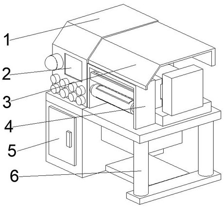
[0028] see Figure 1-Figure 4 , the present invention provides a technical solution: a fully automatic winding device for micro-transformers, comprising a device main body 5, a motor box 1 is fixedly connected to the top of the device main body 5, and an operation panel 2 is fixedly connected to the front of the motor box 1 , the top of the right outer wall of the motor box 1 is fixedly connected with a protective top cover 3, the working position of the installation device 4 can be protected by the protective top cover 3, thereby reducing the accumulation of dust on the surface of the installation device 4 during operation, so that the dust is not easy to In the process of winding, it adheres to the surface of the line, thereby improving the work efficiency of the subsequent use of the line, and the protective top cover 3 is closely attached to the motor box 1, which is convenient to increase the tightness of the connection position of the protective top cover 3 and avoids the...
Embodiment 2
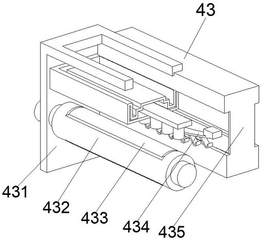
[0034] see Figure 5-Figure 6, On the basis of the first embodiment, the present invention provides a technical solution: the cutting device 435 includes a placing frame 81, and a horizontal bearing plate 82 is fixedly connected to the middle position of the inner cavity bottom of the placing frame 81, and the horizontal bearing plate 82 It is closely attached to the placing frame 81, so that the horizontal bearing plate 82 is kept in a horizontal state under the support of the placing frame 81, thereby accelerating the speed of line cutting after the winding is completed, and the horizontal bearing plate 82 and the vertical lifting body 85. There is a small amount of space, which avoids the problem of collision with the horizontal bearing plate 82 when the vertical lifting body 85 rises and falls, thereby prolonging the service life of the horizontal bearing plate 82. The vertical lifting body 85 is fixedly connected to the side, and the vertical lifting body 85 drives the re...
Embodiment 3
[0038] see Figure 1-Figure 6 , on the basis of Embodiment 1 and Embodiment 2, the present invention provides a technical solution: a method of using a fully automatic winding device for a micro-transformer, step 1: install the device and balance the support frame 6. Make a fixed connection with the installation device 4, place the beginning of the line on the installation device 4, and connect the motor box 1 and the installation device 4 for rotation, so that the motor inside the motor box 1 drives the installation device 4 to wrap the line;
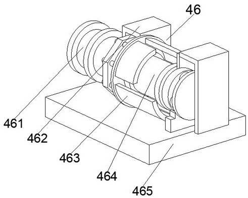
[0039] Step 2: Guide the line tension after adjustment by the guide limit roller 44, and as the line is positioned by the sensor on the sensor mounting member 45, the guide limit roller 44 and the tensioning device 43 are rotated and connected, and Place the sensor mounting member 45 on the tensioning device 43 and guide it below the limit roller 44, and fix the mounting plate 41 with the processing platform 42;
[0040] Step 3: Use t...
PUM
 Abstract
Description
Claims
Application Information
 - R&D Engineer
- R&D Manager
- IP Professional
- Industry Leading Data Capabilities
- Powerful AI technology
- Patent DNA Extraction
Browse by: Latest US Patents, China's latest patents, Technical Efficacy Thesaurus, Application Domain, Technology Topic, Popular Technical Reports.
© 2024 PatSnap. All rights reserved.Legal|Privacy policy|Modern Slavery Act Transparency Statement|Sitemap|About US| Contact US: help@patsnap.com