Production and preparation method of acid and alkali resistant electronic cloth
An electronic cloth, acid and alkali resistance technology, applied in the direction of binding materials, textiles and paper making, fiber processing, etc. Storage or transportation, prevention of bending deformation, cost reduction effect
- Summary
- Abstract
- Description
- Claims
- Application Information
AI Technical Summary
Problems solved by technology
Method used
Image
Examples
Embodiment 1
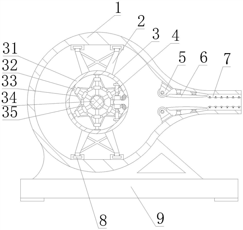
[0049] like figure 1 As shown in -6, the present invention provides a production and preparation method of acid and alkali resistant electronic cloth, and the production and preparation method of acid and alkali resistant electronic cloth includes the following steps:
[0050] Step 1: prepare raw materials;
[0051] Step 2: melting the raw material;
[0052] Step 3: Vacuum defoaming treatment;
[0053] Step 4: Coating sizing agent;
[0054] Step 5: Drawing, weft;
[0055] Step 6: Finishing processing;
[0056] Step 7: Detect, pack and store.
[0057] The second step includes: putting the prepared raw materials into a melting device, and heating the raw materials to melt them.
[0058] The third step includes: transferring the melted raw materials to the vacuum defoaming equipment, and adding the reagents required for the defoaming treatment to the raw materials according to the ratio of sodium sulfate: calcium sulfate: sodium nitrate = 6:3:1. The melted raw material is ...
Embodiment 2
[0070] like figure 1 As shown in -6, on the basis of Embodiment 1, the present invention provides a technical solution: preferably, the baling device includes a packaging device box 1, and a bracket leg 9 is fixedly connected to the bottom of the outer wall of the packaging device box 1, and the packaging device box is 1. The upper and lower sides of the inner cavity are fixedly installed with rails 8, the top of the rails 8 is fixedly installed with a bracket structure 2, the inner wall of the right bracket structure 2 is rotatably connected with a bundling structure 3, and the inner wall of the right bracket structure 2 is connected with the bundling structure. The left end of 3 is plugged in, the right side of the inner cavity of the baling structure 3 is fixedly installed with the pressure plate structure 4, the right side of the inner wall of the packaging device box 1 is fixedly installed with the feeding port guide plate 7, and the right side of the inner wall of the pac...
Embodiment 3
[0073] like figure 1 As shown in -6, on the basis of Embodiment 1, the present invention provides a technical solution: preferably, the baling structure 3 includes a motor 36, the left side of the motor 36 is fixedly installed on the right side of the packaging device box 1, and the motor 36 The left end of the rotating shaft is fixedly connected with a hexagonal column 38, the left end of the hexagonal column 38 is inserted with a hexagonal tube sleeve 37, the left end of the hexagonal tube sleeve 37 is fixedly connected with a rotating shaft 34, and the outer wall of the rotating shaft 34 is fixedly connected with a support rod 32 , the end of the support rod 32 is fixedly installed with the baling box 31, the middle part of the outer wall of the support rod 32 is fixedly installed with a reinforcement ring rod 35, and the outer wall of the reinforcement ring rod 35 is located between the support rod 32 and the support rod 32 is fixedly installed with a Reinforce the diagona...
PUM
 Abstract
Description
Claims
Application Information
 - R&D
- Intellectual Property
- Life Sciences
- Materials
- Tech Scout
- Unparalleled Data Quality
- Higher Quality Content
- 60% Fewer Hallucinations
Browse by: Latest US Patents, China's latest patents, Technical Efficacy Thesaurus, Application Domain, Technology Topic, Popular Technical Reports.
© 2025 PatSnap. All rights reserved.Legal|Privacy policy|Modern Slavery Act Transparency Statement|Sitemap|About US| Contact US: help@patsnap.com


