Rewinding device for stripping base cloth
A technology of winding device and base cloth, which is applied in the directions of drying gas arrangement, winding strips, transportation and packaging, etc., can solve the problems of low winding efficiency, degraded peeling quality, and hindered peeling, and achieves high work efficiency and operation. Easy and precise adjustment
- Summary
- Abstract
- Description
- Claims
- Application Information
AI Technical Summary
Problems solved by technology
Method used
Image
Examples
Embodiment 1
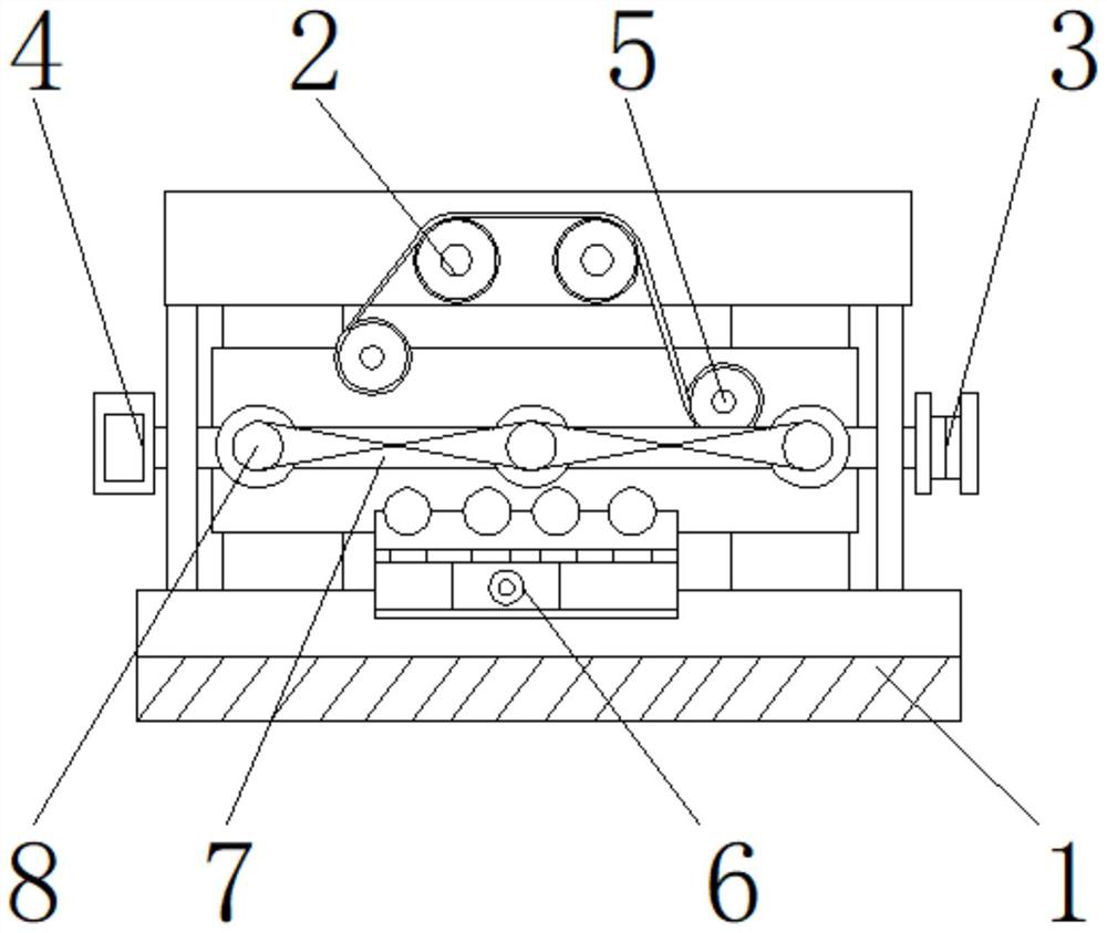
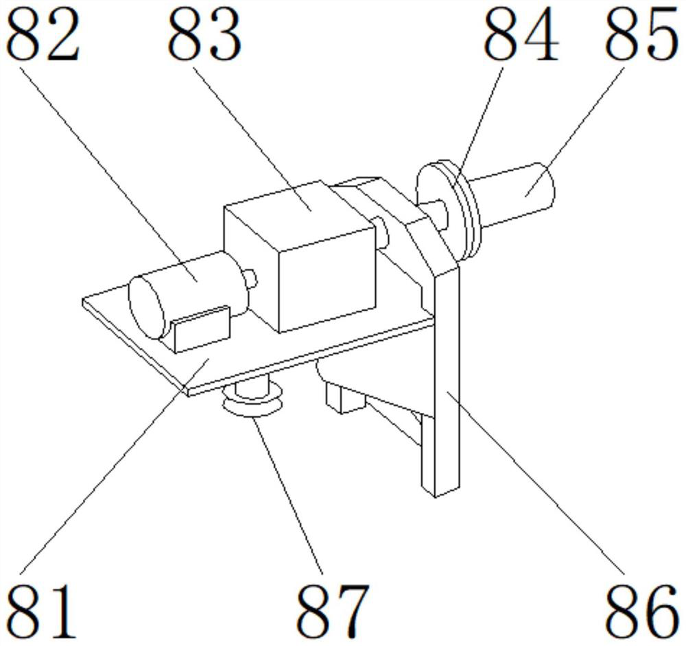
[0027] like Figure 1-5 As shown, the present invention provides a rewinding device for base fabric peeling, including a main body 1, an air-drying device 6 is arranged on the upper end of the main body 1, a guide roller 7 is arranged above the air-drying device 6, and the front end of the guide roller 7 is arranged with a retractor Rolling device 8, one side of the guide roller 7 is provided with a deviation correction device 3, the other side of the guide roller 7 is provided with a controller 4, a steel wheel 5 is provided above the guide roller 7, and a rubber wheel 2 is provided above the steel wheel 5 The winding device 8 includes a base plate 81, a motor 82, a braking mechanism 83, a bearing 84, a roll 85, a support frame 86, a supporting shaft roller 87, the motor 82 is located at the upper end of the base plate 81, and the supporting shaft roller 87 is located at the lower end of the base plate 81 A bolt is provided between the bottom plate 81 and the motor 82, the up...
Embodiment 2
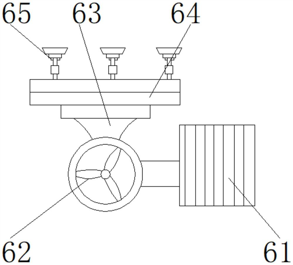
[0030] like Figure 1-5 As shown, on the basis of Embodiment 1, the present invention provides a technical solution: preferably, the air drying device 6 includes a driving device 61, a fan 62, an air supply duct 63, a mounting frame 64, and a spray head 65, and the fan 62 is located in the driving device. On one side of 61, the air supply duct 63 is located at the upper end of the fan 62, the installation frame 64 is located at the upper end of the air supply duct 63, the nozzle 65 is located at the upper end of the installation frame 64, the surface of the installation frame 64 is provided with a through hole, and the lower end of the nozzle 65 passes through. The through hole is fixedly connected to the upper end of the mounting frame 64, a flange is arranged between the air supply duct 63 and the fan 62, the lower end of the air supply duct 63 is fixedly connected to the upper end of the fan 62 through the flange, and the input end of the fan 62 passes through The wires are...
Embodiment 3
[0033] like Figure 1-5As shown, on the basis of Embodiment 1, the present invention provides a technical solution: preferably, the deviation correction device 3 includes a mounting block 31, a slot 32, a vertical contrast plate 33, a fixed plate 34, a deviation correction module 35, and an induction device 36. , the slot 32 is located at the upper end of the mounting block 31, the deviation correction module 35 is located at the upper end of the slot 32, the fixed plate 34 is located at the upper end of the deviation correction module 35, the vertical contrast plate 33 is located at the rear end of the deviation correction module 35, and the sensing device 36 is located at the fixed plate 34 On one side, a welding block is arranged between the deviation correction module 35 and the vertical comparison plate 33, the rear end of the deviation correction module 35 is fixedly connected to the upper end of the vertical comparison plate 33 through the welding block, and a connection...
PUM
 Abstract
Description
Claims
Application Information
 - Generate Ideas
- Intellectual Property
- Life Sciences
- Materials
- Tech Scout
- Unparalleled Data Quality
- Higher Quality Content
- 60% Fewer Hallucinations
Browse by: Latest US Patents, China's latest patents, Technical Efficacy Thesaurus, Application Domain, Technology Topic, Popular Technical Reports.
© 2025 PatSnap. All rights reserved.Legal|Privacy policy|Modern Slavery Act Transparency Statement|Sitemap|About US| Contact US: help@patsnap.com


