Eureka AIR delivers breakthrough ideas for toughest innovation challenges, trusted by R&D personnel around the world.

Woven fabric

Inactive Publication Date: 2013-10-03
TOYOTA BOSHOKU KK
View PDF9 Cites 58 Cited by
  • Summary
  • Abstract
  • Description
  • Claims
  • Application Information

AI Technical Summary

Benefits of technology

The patent text describes a structure for a woven fabric that prevents the disconnection of a low shrinkage yarn, which is important for maintaining the fabric's strength. The structure achieves this by inducing the low shrinkage yarn in a specific direction and bending it, which prevents it from deviating from its position. This inducing process also improves the load bearing capacity of the low shrinkage yarn. The woven fabric made using this structure has excellent aesthetics, with the low shrinkage yarn being invisible from one side in the thickness direction. Overall, this structure allows for a high-quality woven fabric that is both strong and aesthetically pleasing.

Problems solved by technology

Because the woven fabric described in JP 2010-261116 A must have the shrinking portion that shrinks relatively easily, the aesthetics may be diminished due to the fact that this shrinkage portion shrinks more than the other portions.

Method used


Image

  • Woven fabric
  • Woven fabric
  • Woven fabric

Examples


Embodiment Construction

[0028]Example embodiments of the invention will now be described with reference to the accompanying drawings. A seat cover of a vehicle seat will be given as an example of that to which a woven fabric 1 according to the example embodiments of the invention is applied. Hereinafter, various structures will be described in detail, with a woven fabric used as a seat cover of a vehicle seat as an example.

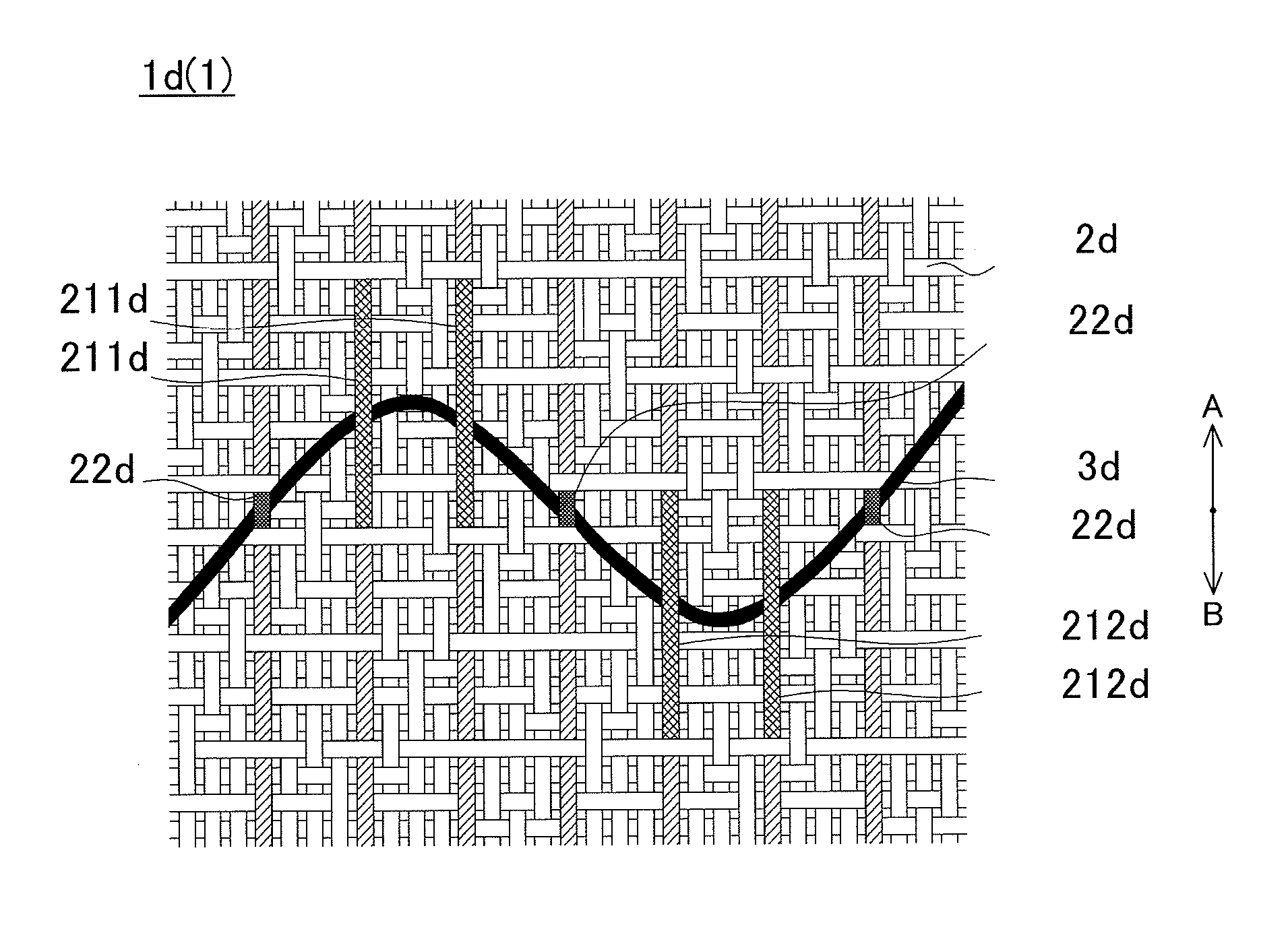
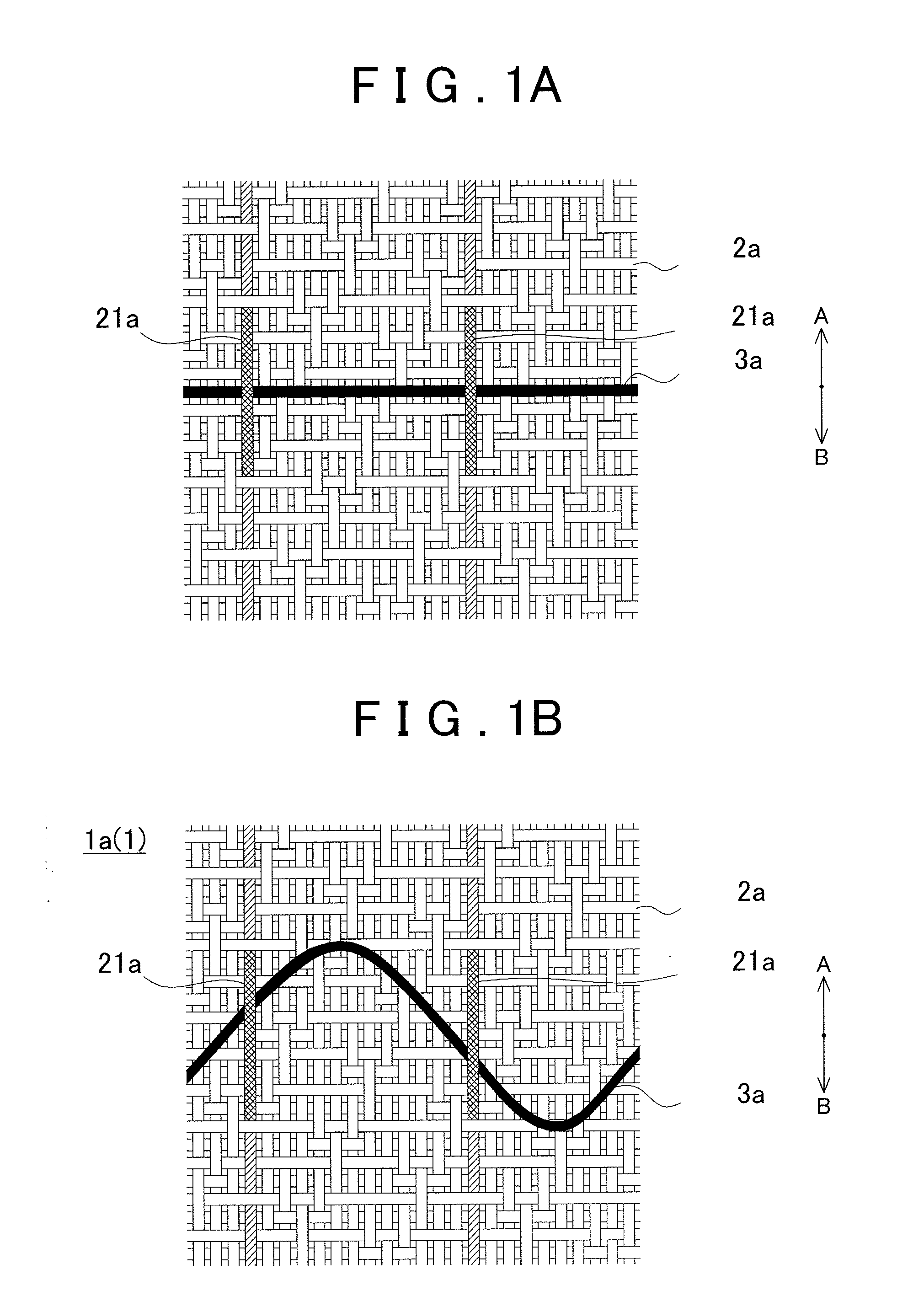
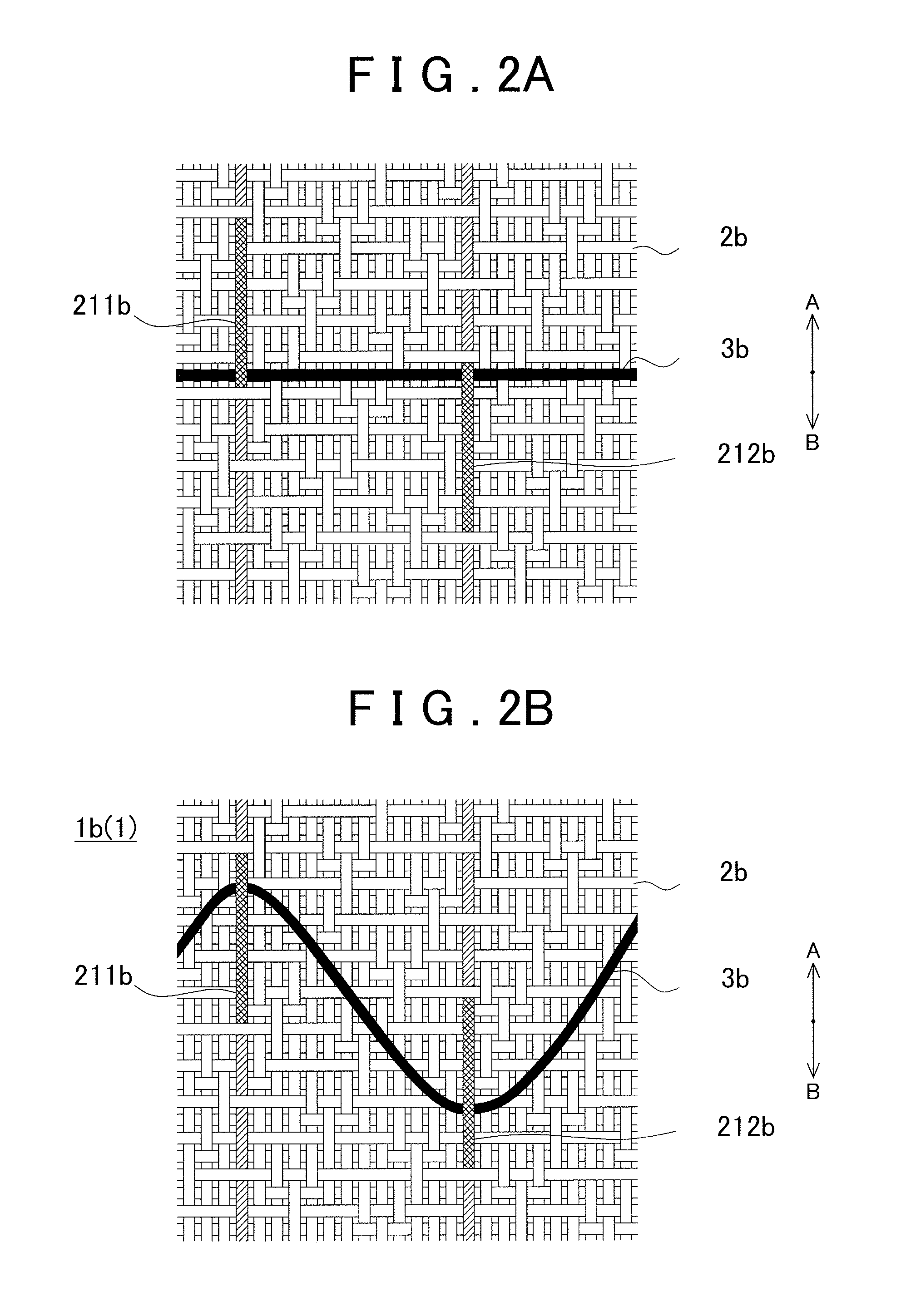
[0029]The woven fabric 1 according to the example embodiments includes a high shrinkage yarn 2 and a low shrinkage yarn 3. The high shrinkage yarn 2 is a yarn made of material with a relatively high shrinkage ratio (i.e., it shrinks easily) (compared to the low shrinkage yarn 3). The low shrinkage yarn 3 is a yarn made of material with a relatively low shrinkage ratio (i.e., it does not shrink easily) (compared to the high shrinkage yarn 2). The woven fabric 1 according to the example embodiments is such that a portion that will be the base of the woven fabric is formed by the high shrin...


PUM

PropertyMeasurementUnit
Shrinkageaaaaaaaaaa
Ratioaaaaaaaaaa

Abstract

A woven fabric having a high shrinkage yarn that has a predetermined shrinkage ratio and a low shrinkage yarn that has a relatively lower shrinkage ratio than the high shrinkage yarn, includes an inductive portion that is formed by the high shrinkage yarn, and allows displacement in a planar direction. At least a portion of the low shrinkage yarn is engaged with the inductive portion and bent in the planar direction.

Description

INCORPORATION BY REFERENCE[0001]The disclosure of Japanese Patent Application No. 2012-072652 filed on Mar. 28, 2012 including the specification, drawings and abstract is incorporated herein by reference in its entirety.BACKGROUND OF THE INVENTION[0002]1. Field of the Invention[0003]The invention relates to a woven fabric having a high shrinkage yarn that has a relatively high shrinkage ratio and a low shrinkage yarn that has a relatively low shrinkage ratio.[0004]2. Description of Related Art[0005]A woven fabric having an insulating fiber (high shrinkage yarn) and conductive wire (low shrinkage yarn), as described in Japanese Patent Application Publication No. 2010-261116 (JP 2010-261116 A) below is known. JP 2010-261116 A describes a woven fabric having a structure in which a shrinking portion is provided at a predetermined location formed by an insulating fiber. This shrinking portion tends to shrink more at the predetermined location than at other locations. Also, the conductive...

Claims


Application Information

Patent Timeline
IPC IPC(8): D03D1/00D03D15/567
CPCD03D1/00D03D1/0088D03D11/00D10B2505/08D10B2101/12D10B2101/20D10B2401/16D03D15/04Y10T442/3179Y10T442/3195Y10T442/3976D03D15/567
Inventor ITO, MITSUYOSHIKUNISADA, HIDEAKI
Owner TOYOTA BOSHOKU KK
Why Eureka
Eureka Blog
Learn More