Eureka AIR delivers breakthrough ideas for toughest innovation challenges, trusted by R&D personnel around the world.

Rubber gasket production process

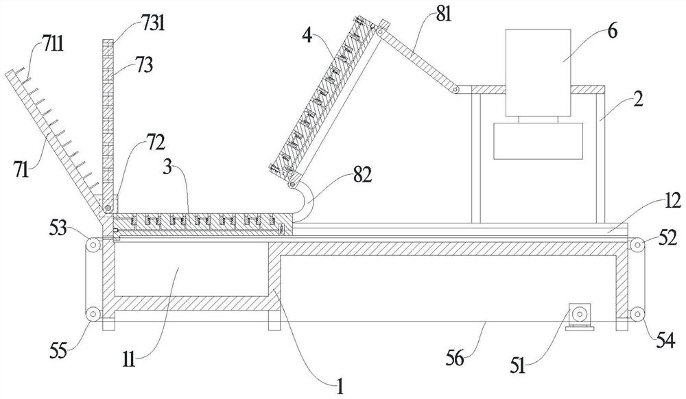
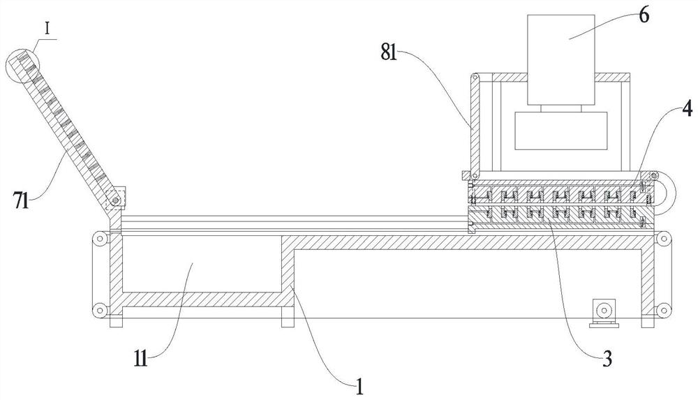
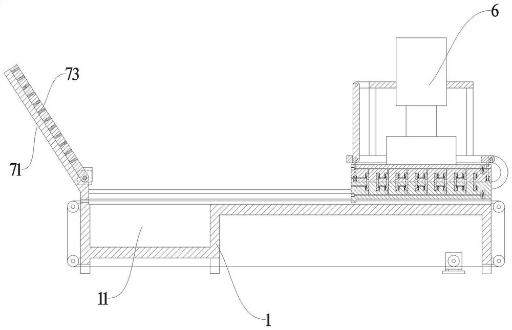
A technology of rubber gasket and production process, applied in the field of rubber gasket production technology, can solve the problems of low efficiency, large workload of manual cutting and high mold temperature, and achieve the effect of convenient collection and cutting and saving labor.

Pending Publication Date: 2022-07-29
于宗玄
View PDF0 Cites 0 Cited by
  • Summary
  • Abstract
  • Description
  • Claims
  • Application Information

AI Technical Summary

Problems solved by technology

[0003] 1. The existing rubber gaskets are generally produced by vulcanization molding; the placement of the rubber strips needs to be done manually, and the existing mold is divided into upper and lower parts. The workers need to hold the rubber strips deep into the two molds to place the rubber The strips are placed in the corresponding position. Since the vulcanization molding production method needs to maintain a certain high temperature, the mold temperature is very high. The workers are easy to burn during the process of placing the rubber strips, which is very dangerous;
[0004] 2. After the rubber gasket is vulcanized and formed, it is necessary to manually remove the produced rubber gasket. Due to the high temperature of the mold, manual cutting is dangerous, and the number of rubber gaskets is large, and the workload of manual cutting Larger and lower efficiency;
[0005] 3. The existing rubber gaskets will have burrs after vulcanization and molding production, which need to be cleaned manually in the later stage before they can be used. Manual cleaning of burrs is boring and inefficient, and it is easy to cause damage to the rubber gaskets, affecting Its use effect

Method used


Image

  • Rubber gasket production process
  • Rubber gasket production process
  • Rubber gasket production process

Examples


Embodiment Construction

[0035] The technical solutions in the embodiments of the present invention will be clearly and completely described below with reference to the accompanying drawings in the embodiments of the present invention. Obviously, the described embodiments are only a part of the embodiments of the present invention, rather than all the embodiments. Based on the embodiments of the present invention, all other embodiments obtained by those of ordinary skill in the art without creative efforts shall fall within the protection scope of the present invention.

[0036] It should be noted that when a component is referred to as being "mounted on" another component, it can be directly on the other component or there may also be an intervening component. When a component is considered to be "set on" another component, it may be directly set on the other component or there may be a co-existing centered component. When a component is said to be "fixed" to another component, it may be directly fixed...


PUM


Abstract

The invention relates to a rubber gasket production process, a processing device is applied for processing, the rubber gasket production process comprises the steps that S1, a lower mold is moved to a second working position, and a rubber strip is manually placed on the lower mold; s2, the lower mold is moved to a first working position, and the upper mold is arranged on the lower mold in a covering mode; s3, the vulcanization forming machine is started, the upper mold extrudes the lower mold, the upper mold is heated, and rubber is subjected to vulcanization forming; and S5, the lower die is moved to a second working position, the discharging mechanism is started, and the rubber gasket on the lower die is taken down. The device has the advantages that the chain is used for driving the lower mold to move, and the connecting rod is hinged to the upper mold and the mounting frame, so that when the lower mold moves to the second working position, the upper mold is turned over under the action of the connecting rod, and the risk of scalding when the rubber strips are manually placed can be avoided.

Description

technical field [0001] The invention relates to the technical field of rubber gaskets, in particular to a production process of rubber gaskets. Background technique [0002] The rubber industry is one of the important basic industries of the national economy. It not only provides people with daily necessities, medical and other light industrial rubber products, but also provides heavy and emerging industries such as mining, transportation, construction, machinery, and electronics. Various rubber production equipment or rubber parts. Due to its oil resistance, acid and alkali resistance, cold and heat resistance, and aging resistance, rubber gaskets are usually used as seals. In the prior art, the production of rubber gaskets often has the following problems: [0003] 1. The existing rubber gaskets are generally produced by vulcanization molding; the placement of the rubber strips needs to be done manually, and the existing molds are divided into upper and lower parts. The ...

Claims


Application Information

Patent Timeline
IPC IPC(8): B29C43/50B29C43/02B29C35/02B29C43/32B29C43/36B29C37/02
CPCB29C43/50B29C43/02B29C35/02B29C43/32B29C43/36B29C37/02B29C2043/503
Inventor 于宗玄张卫国
Owner 于宗玄
Why Eureka
Eureka Blog
Learn More