
Intelligent welding seam shot blasting machine

A shot blasting machine and shot blasting machine technology, which is applied in abrasive jet machine tools, metal processing equipment, used abrasive processing devices, etc. problems, to achieve the effect of improving shot blasting efficiency and shot blasting effect, improving the degree of intelligence, and improving the effect of use

Active Publication Date: 2022-07-29
江苏锐达科技有限公司
View PDF23 Cites 0 Cited by
  • Summary
  • Abstract
  • Description
  • Claims
  • Application Information

AI Technical Summary

Problems solved by technology

[0005] The purpose of the present invention is to provide an intelligent welding seam shot blasting machine, which effectively supports and fixes the cylindrical or tubular workpiece through the positioning drive assembly and realizes the rotation of the workpiece during the shot blasting process, which significantly improves the weld seam blasting process. The efficiency of shot operation, through the cleaning and recovery components, the functions of brush cleaning, blast dust removal, shot collection and shot lifting and conveying are integrated and run synchronously. The functions are diverse, which significantly improves the use effect, and through the cleaning analysis and diagnosis The combination of analysis has significantly improved the intelligence of the equipment, and solved the problems of low processing efficiency, hard operation, difficulty in realizing the recycling of shot material in the existing technology, and the difficulty in comprehensively analyzing the shot blasting process and shot cleaning process to realize automatic cleaning. Adjustment, the problem of low intelligence

Method used

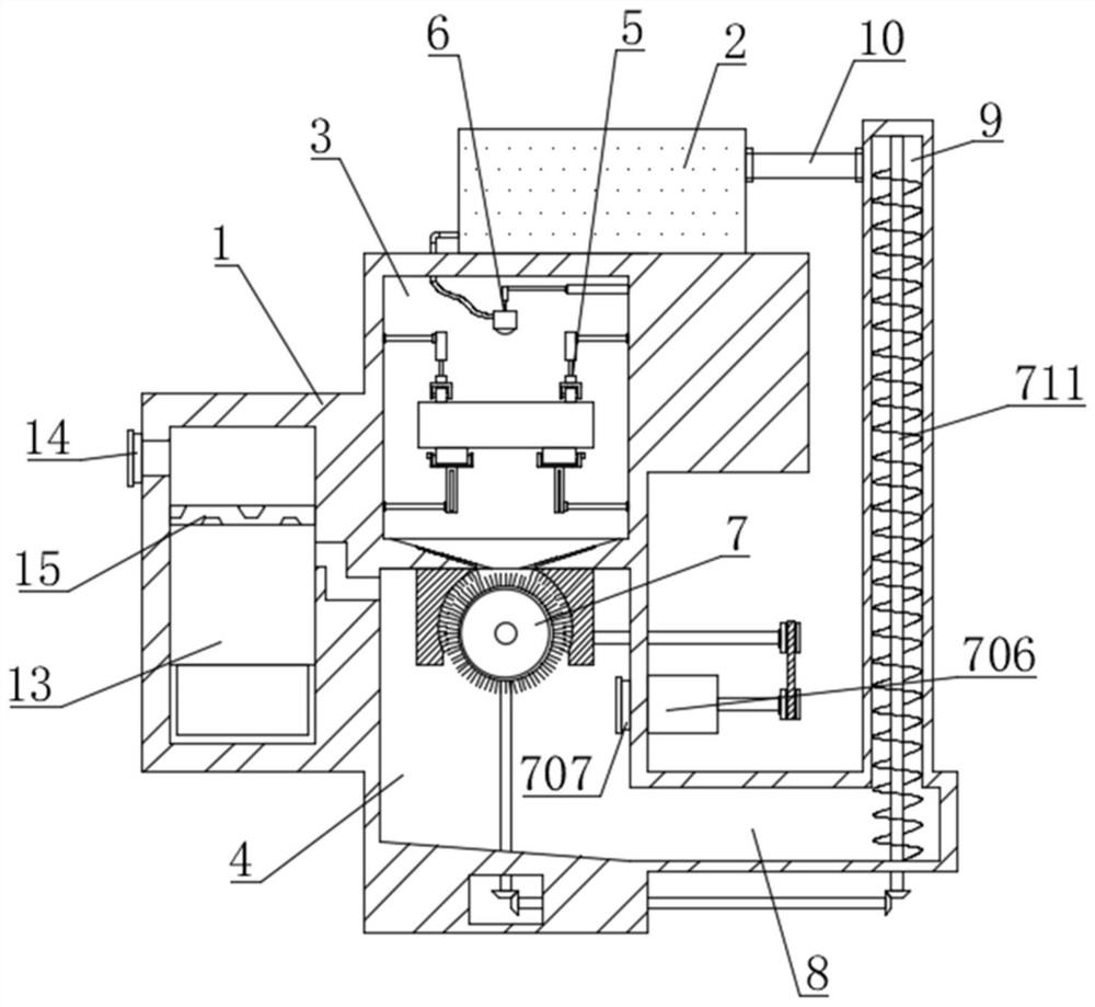

Image

  • Intelligent welding seam shot blasting machine
  • Intelligent welding seam shot blasting machine
  • Intelligent welding seam shot blasting machine

Examples


Embodiment 1

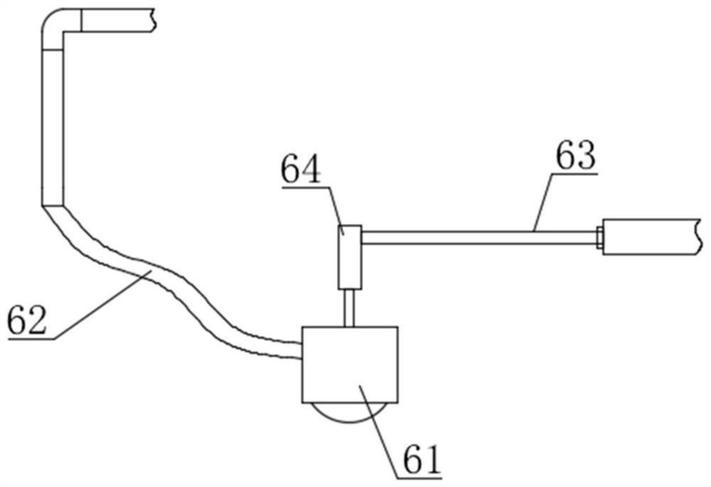
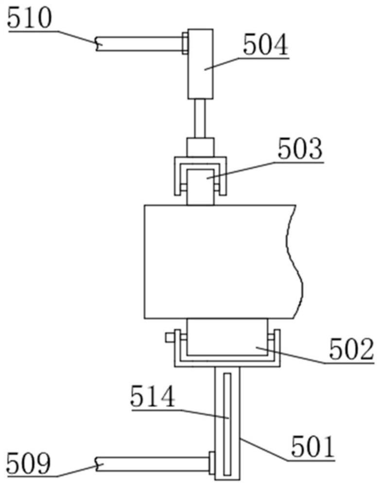
[0048] like Figure 1-9 As shown in the figure, an intelligent weld shot blasting machine proposed by the present invention includes a shot blasting machine body 1, the top of the shot blasting machine body 1 is fixedly installed with a shot blasting box 2 by bolts, and the shot blasting box 2 stores a shot blasting machine. The shot blasting machine body 1 is provided with a shot blasting room 3 and a clean room 4, and the shot blasting room 3 is located above the clean room 4 and communicated with it through the lower hopper 11, and the lower hopper 11 is provided with a feeding plate 12. The shot blasting chamber 3 is provided with a shot blasting device 6. Specifically, the shot blasting device 6 includes a shot blasting head 61, a lateral push rod 63 and a lifting push rod 64. The lateral push rod 63 is arranged in the shot blasting chamber 3, and the The push rod 64 is connected to the horizontal push rod 63 and the shot peening head 61 , and the shot peening head 61 and...

Embodiment 2

[0055] like Figure 10 As shown, the difference between this embodiment and Embodiment 1 is that a control panel is installed on the shot blasting machine body 1, and the control panel includes a data acquisition unit, a processor, a material removal analysis unit, a diagnosis adjustment unit and an intelligent control unit; The collection unit collects the clearing data, and sends the clearing data to the processor; wherein, the clearing data includes the pressure value of the receiving plate 12 (the pressure value is the weight of the pellets carried above the receiving plate 12, which is determined by the It is detected by the gravity sensor) and the ejection speed value of the shot blasting machine 6 (the ejection speed value is the ejection speed of the shot material during shot blasting, which is detected by the ejection speed sensor), and the processor generates a clearing analysis signal of the returned material, and the The clearing analysis signal and clearing data a...

Embodiment 3

[0062] like Figure 10 As shown, the difference between this embodiment and Embodiment 1 and Embodiment 2 is that the control panel further includes a diagnosis and adjustment unit, and the data acquisition unit collects the diagnosis data, and sends the diagnosis data to the processor; wherein, the diagnosis data includes a shot blasting machine. The throwing distance value of 6 and the injection speed value of the shot blasting machine 6; the processor generates the adjustment analysis signal of the shot blasting machine, and sends the adjustment analysis signal and the diagnosis data to the diagnosis analysis unit; the diagnosis analysis unit is used for adjustment analysis, adjustment The analysis process is as follows:

[0063] Step X1: Receive the throw distance value of the shot blasting wheel 6, and mark the throwing distance value of the shot blasting wheel 6 as PJZ; wherein, the throwing distance value of the shot blasting wheel 6 represents the distance between the ...


PUM


Abstract

The invention belongs to the technical field of shot blasting machines, aims at solving the problems that in the prior art, the machining efficiency is low, operation is hard, recycling of shots is difficult to achieve, the shot blasting process and the shot cleaning process are difficult to comprehensively analyze to achieve automatic adjustment, and the intelligent degree is low, and particularly relates to an intelligent welding seam shot blasting machine which comprises a shot blasting machine body. A shot blasting chamber and a cleaning chamber are formed in the shot blasting machine body, and a shot blasting device and a positioning driving assembly are arranged in the shot blasting chamber; a cleaning and recycling assembly is arranged in the shot blasting machine body; according to the shot blasting machine, a cylindrical or tubular machined part is effectively supported and fixed through the positioning driving assembly, rotation of the machined part in the shot blasting process is achieved, the functions of brushing and sweeping cleaning, blowing dust removal cleaning, shot collection and shot lifting and conveying are integrated and synchronously operated through the cleaning and recycling assembly, and the using effect is remarkably improved; and material cleaning analysis and diagnostic analysis are combined, so that the intelligent degree of the equipment is remarkably improved.

Description

technical field [0001] The invention relates to the technical field of shot blasting machines, in particular to an intelligent weld shot blasting machine. Background technique [0002] Shot blasting machine refers to the mechanical equipment that uses the high-speed projectile thrown by the shot blasting machine to clean or strengthen the surface of the workpiece. The welding seam is the joint part formed by the welding of the welding parts. At present, a shot blasting machine is generally required to process the welding seam of the cylindrical or tubular workpiece. [0003] In the prior art, when the welding seam is processed by a shot blasting machine, the workpiece needs to be fixed by the clamping structure first, and then the welding seam part of the workpiece needs to be shot blasted by the shot blasting machine. Most of the welds are in the shape of a circle. During the whole processing process of a circle of welds, the workpiece needs to be clamped and turned over m...

Claims


Application Information

Patent Timeline
Patent Type & Authority Applications(China)
IPC IPC(8): B24C1/08B24C3/18B24C9/00
CPCB24C1/08B24C3/18B24C9/00B24C9/003B24C9/006Y02P70/10
Inventor 董晨赵剑袁刚吕娜朱学贵
Owner 江苏锐达科技有限公司
Learn More