Wire stripping and bending device for electrical engineering and use method of wire stripping and bending device
A bending device and electrical engineering technology, which is applied in the direction of dismantling/armouring cable equipment, etc., can solve the problems of slow wire stripping speed, reduce wire processing speed, and inability to do it at the same time, and achieve the effect of increasing the stripping speed
- Summary
- Abstract
- Description
- Claims
- Application Information
AI Technical Summary
Problems solved by technology
Method used
Image
Examples
Embodiment 1
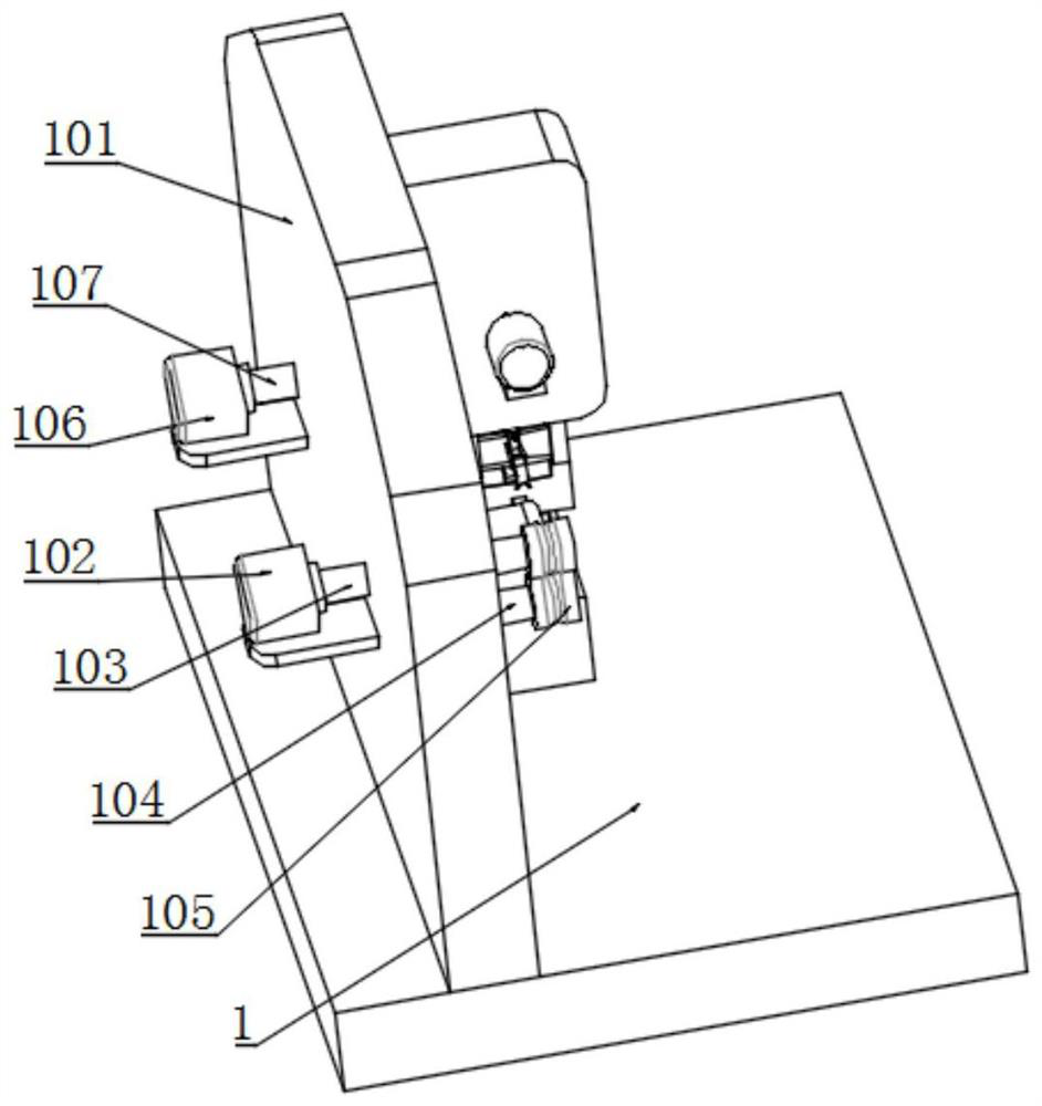
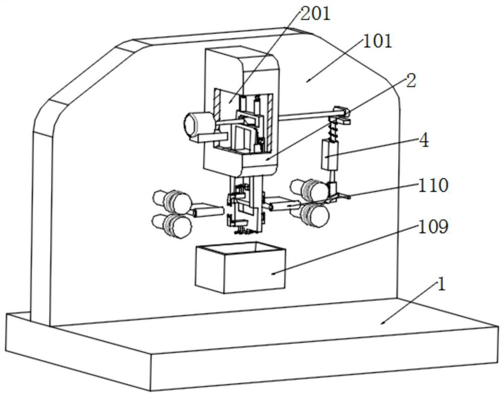
[0037] like Figure 1 to Figure 8 As shown, the embodiment of the present invention provides a wire stripping and bending device for electrical engineering, including a workbench 1, the top of the workbench 1 is fixedly connected with a fixing plate 101, and one side of the fixing plate 101 is fixed An installation box 2 is connected, the installation box 2 is provided with an installation cavity 201, the bottom inner wall of the installation cavity 201 is provided with two sliding holes, and a sliding frame 202 and a movable frame 203 slide in the two sliding holes. The sliding frame 202 and the movable frame 203 are slidably connected. The sliding frame 202 and the movable frame 203 are both fixedly connected with a cutter 204. A rack 211 is fixedly connected to one side of the frame 202 and the movable frame 203, a gear 212 is engaged with the two racks 211, and one side of the gear 212 is keyed with a rotating column 213, and the rotating column One side of the 213 is rot...
Embodiment 2
[0047] The present embodiment discloses a method for using a wire stripping and bending device for electrical engineering, including the following steps:
[0048] Step 1: Pass one end of the wire through the two feeding wheels 105 and enter the wire tube 110 at the feeding end. The first servo motor 102 drives the feeding shaft 103 and the feeding wheel 105 to rotate to transport the wire, so that the wire passes through the two in turn. The cutter 204, the wire tube 110 at the discharge end and the two discharge wheels 108;
[0049] Step 2: The second servo motor 205 drives the drive shaft 206 and the cam 207 to rotate, and the cam 207 rotates to drive the sliding frame 202 and the movable frame 203 to move in the opposite direction, so that the sliding frame 202 and the movable frame 203 drive the two cutters 204 to move closer to each other. The wire is cut, and the movement of the two cutters 204 drives the fixed block 3, the sliding block 301 and the blade 302 to move, th...
PUM
 Abstract
Description
Claims
Application Information
 - R&D
- Intellectual Property
- Life Sciences
- Materials
- Tech Scout
- Unparalleled Data Quality
- Higher Quality Content
- 60% Fewer Hallucinations
Browse by: Latest US Patents, China's latest patents, Technical Efficacy Thesaurus, Application Domain, Technology Topic, Popular Technical Reports.
© 2025 PatSnap. All rights reserved.Legal|Privacy policy|Modern Slavery Act Transparency Statement|Sitemap|About US| Contact US: help@patsnap.com


