Ejector optimization method and ejector
An optimization method and ejector technology, applied in the ejector optimization, ejector field, can solve the problems of abnormal system operation, unstable equipment operation, shutdown, etc.
- Summary
- Abstract
- Description
- Claims
- Application Information
AI Technical Summary
Problems solved by technology
Method used
Image


Examples
Embodiment 1
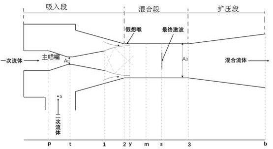
[0043] like figure 1 As shown in the figure, as the primary flow pressure decreases, the mass flow rate of the mixed fluid at the ejector outlet also decreases; for the above problems, this embodiment provides an ejector optimization method; this embodiment mainly focuses on the primary flow pressure fluctuation A calculation model that can maintain the geometric parameters of the main nozzle is proposed. The fluid mixing mechanism inside the injector is as follows: figure 2 For the convenience of description and distinction, in this implementation, the ejector model is divided into a suction section, a mixing section and a diffuser section, and the relevant control equations and solution process of the model are as follows:
[0044] like figure 2 As shown, the control equation from the injector outlet to the interface between the mixing section and the diffuser section in this embodiment is as follows:
[0045] (1)
[0046] The interface between the mixing section and...
Embodiment 2
[0081] The present embodiment provides an injector, including a main nozzle, and a mixing section of the injector includes a first cross-section close to the main nozzle, and a second cross-section away from the main nozzle;
[0082] The method of determining the throat cross-sectional area of the main nozzle is as follows: according to the obtained primary flow velocity and secondary flow velocity at the first section, and the primary flow mass flow, and based on the law of conservation of momentum before and after fluid mixing at the second section, determine The cross-sectional area of the main nozzle throat under different primary flow pressures when the mass flow rate of the mixed fluid is constant.
[0083] The main nozzle is a multi-ring main nozzle.
Embodiment 3
[0085] like image 3 As shown, in order to further improve and illustrate the embodiment 2, this embodiment provides an injector, including a main nozzle, the parameters of the main nozzle are obtained by the injector optimization method as described in the embodiment 1;
[0086] In Example 2, the solution equations for the geometric parameters of the main nozzle to maintain a constant mass flow rate of the ejector mixed fluid under different primary flow conditions are obtained by derivation; New injector for mixing fluid mass - dual annular main nozzle injector. Since it is necessary to use main nozzles with different cross-sectional areas to maintain a constant mass flow rate of the mixed fluid under different primary flow conditions, and considering that the injector still needs to have high ejection performance under the set conditions, it is necessary to design a An injector with different cross-sectional area main nozzles under different main nozzles. The realization ...
PUM
 Abstract
Description
Claims
Application Information
 - R&D
- Intellectual Property
- Life Sciences
- Materials
- Tech Scout
- Unparalleled Data Quality
- Higher Quality Content
- 60% Fewer Hallucinations
Browse by: Latest US Patents, China's latest patents, Technical Efficacy Thesaurus, Application Domain, Technology Topic, Popular Technical Reports.
© 2025 PatSnap. All rights reserved.Legal|Privacy policy|Modern Slavery Act Transparency Statement|Sitemap|About US| Contact US: help@patsnap.com