Road and bridge engineering construction surveying equipment

A technology for road and bridge engineering and survey equipment, applied in the field of road and bridge engineering construction survey equipment, can solve problems such as hidden dangers, glare, general safety, etc., and achieve the effect of reducing hidden dangers, ensuring cleanliness, and ensuring integrity

Active Publication Date: 2022-07-22
滨州北海城市开发建设集团有限公司
View PDF7 Cites 1 Cited by
  • Summary
  • Abstract
  • Description
  • Claims
  • Application Information

AI Technical Summary

Problems solved by technology

However, when the existing total station electronic range finder is in use, due to the survey work at the construction site or the laying route, the dust on the site is relatively large, and there is no protective structure on the survey equipment, so the dust is easy to fall on the control panel. Affect normal use and viewing, and when surveying the construction site, it is generally sunny weather, under the action of sunlight, it will cause glare, and it is difficult for the staff to see the values ​​​​on the display screen on the control panel, making observation difficult. There are certain limitations in use. At the same time, when the entire survey equipment is not in use, the support rod at the lower end of the support foot has a sharp point, and the sharp point is directly exposed, which poses a certain safety hazard. It is generally safe to use.

Method used


Image

  • Road and bridge engineering construction surveying equipment
  • Road and bridge engineering construction surveying equipment
  • Road and bridge engineering construction surveying equipment

Examples


Embodiment 1

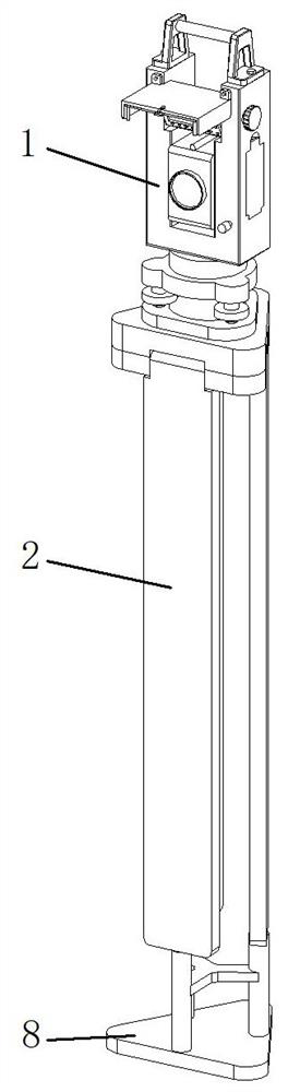
[0031] like Figure 1-Figure 8 As shown, a road and bridge engineering construction survey equipment includes a survey main body 1 and a support foot 2, a survey main body 1 is provided with a measuring device 3, and the survey device 3 is provided with an eyepiece 4, and the upper end position of the survey main body 1 is provided with a control Panel 5, and the control panel 5 is located above the measuring instrument 3, the upper end of the supporting foot 2 is provided with a mounting seat 13, the survey main body 1 is connected to the mounting seat 13, the lower end of the supporting foot 2 is provided with a supporting rod 14, and the survey main body 1 is provided with a supporting rod 14. A protective structure 6 is provided for protecting the control panel 5, a protective structure 8 is provided on the support rod 14, the lower end of the support rod 14 is provided with a tip, the control panel 5 is rotatably connected to the survey main body 1, and the survey main bod...

Embodiment 2

[0034] like Figure 1-Figure 8 As shown, the same or corresponding components as those in the first embodiment are given the corresponding reference numerals as in the first embodiment. For the sake of brevity, only the points of difference from the first embodiment are described below. The difference between the second embodiment and the first embodiment is: Figure 4 , Figure 5 , Image 6 As shown, the protective structure 6 includes a shading plate 601, an installation block 602, a side plate 604 and a rotating protective frame 606. The shading plate 601 is connected to the installation block 602, and the installation block 602 is connected to the survey main body 1. The side plate 604 is arranged on the On the shading plate 601, the rotating protective frame 606 is connected between the side plates 604, and the rotating protective frame 606 is located below the shading plate 601. The protective structure 6 also includes mounting bolts 603 and clamping grooves 605. The m...

Embodiment 3

[0037] like Figure 1-Figure 8 As shown, the same or corresponding components as those in the first embodiment are given the corresponding reference numerals as in the first embodiment. For the sake of brevity, only the points of difference from the first embodiment are described below. The difference between the third embodiment and the first embodiment is as follows: Figure 8 As shown, the protective structure 8 includes a support bottom plate 801 and a protective cover 802, the supporting bottom plate 801 and the protective cover 802 are fixedly connected, and the protective cover 802 is connected to the support rod 14, and the protective structure 8 also includes a through hole 803 and a reinforcing rib 804 , the through holes 803 are opened on the protective sleeve 802, and the protective sleeves 802 are distributed in an annular array on the support base plate 801. The protective sleeve 802 is sleeved on the support rod 14 through the through holes 803, and the reinforc...


PUM


Abstract

The invention discloses road and bridge engineering construction surveying equipment which comprises a surveying main body and supporting legs, a measurer is arranged on the surveying main body, an eyepiece is arranged on the measurer, a control panel is arranged at the upper end of the surveying main body, and the control panel is located above the measurer. The road and bridge engineering construction surveying equipment belongs to the field of surveying equipment, a protection structure can achieve a dustproof effect, a light shielding plate in the protection structure can achieve a light shielding effect, the light shielding plate is matched with a side plate and other structures to achieve the light shielding effect, it is guaranteed that a display screen on a control panel can be clearly checked under sunlight irradiation, and the control panel is more convenient to use. The rotary protection frame can be overhung to achieve the further protection effect, the protection structure can sleeve the supporting rod when the surveying equipment is not used, potential safety hazards are reduced, and when the protection structure sleeves the supporting rod, the protection structure can achieve the supporting effect, and workers can have a rest midway when carrying the surveying equipment.

Description

technical field [0001] The invention relates to the field of survey equipment, in particular to a road and bridge engineering construction survey equipment. Background technique [0002] Road and bridge engineering refers to the survey, design, construction, maintenance, management and other work of highways and bridges. Road and bridge engineering can also be regarded as a kind of work for road and bridge construction. In the construction of road and bridge projects, in addition to the use of many construction equipment, it is also necessary to survey the construction site and laying routes before construction, so survey equipment is used. In the existing survey equipment for road and bridge engineering construction, when measuring the distance, a total-station electronic distance meter is generally used for survey work. The total-station electronic distance meter is mainly composed of the survey body and the support feet. When in use, install the survey body on the suppor...

Claims


Application Information

Patent Timeline
Patent Type & Authority Applications(China)
IPC IPC(8): G01C15/00F16M11/04F16M11/22
CPCG01C15/00F16M11/04F16M11/22
Inventor 贾金生赵林香李玉强
Owner 滨州北海城市开发建设集团有限公司
Why Eureka
Try Eureka