Measuring device for urban planning
A measurement device and urban planning technology, which is applied in the direction of measurement, wellbore/well components, earthwork drilling and production, etc., and can solve problems affecting measurement accuracy, etc.
- Summary
- Abstract
- Description
- Claims
- Application Information
AI Technical Summary
Problems solved by technology
Method used
Image
Examples
Embodiment 1
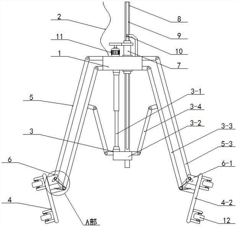
[0051] like figure 1 , 2 As shown, this embodiment includes a base 1 and a hanging rope 2, wherein the hanging rope 2 is fixedly arranged on the base 1, and it also includes:
[0052] A display part 3, the said display part 3 is arranged on the base 1;
[0053] a support member 4, the support member 4 is arranged on the end of the display member 3 away from the base 1;
[0054] An angle limiter 5, the angle limiter 5 is arranged on the base 1, and its end away from the base 1 is arranged on the display member 3;
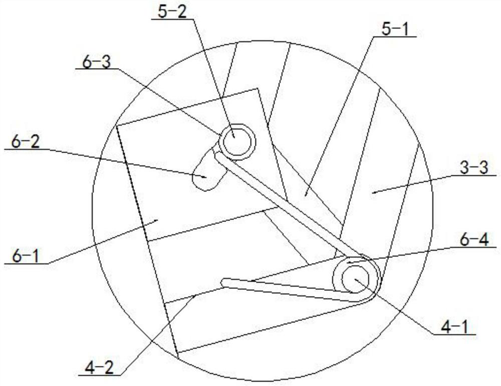
[0055] The angle buffer 6, the angle buffer 6 is arranged on the support 4, and is connected with the angle limiter 5;
[0056] A threaded sleeve 7, the threaded sleeve 7 is screwed through the bearing on the base 1;
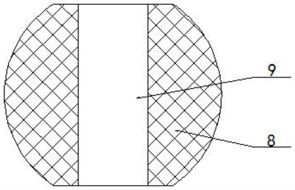
[0057] A threaded rod 8, the threaded rod 8 is inserted into the threaded sleeve 7 by screwing, and the threaded rod 8 is provided with a guide groove 9;
[0058] A guide rod 10, the guide rod 10 is fixed on the base 1 by screws, and the guide rod...
Embodiment 2
[0062] like figure 1 , 4 As shown, on the basis of the above-mentioned embodiment 1, the described display element 3 includes:
[0063] The hydraulic rod 3-1, the hydraulic rod 3-1 is fixed on the lower surface of the base 1 by screws, and the output end of the hydraulic rod 3-1 is set downward;
[0064] The connecting seat 3-2, the connecting seat 3-2 is screwed on the output shaft of the hydraulic rod 3-1 through the rotating shaft, and the connecting seat 3-2 is movably sleeved on the lower end of the threaded rod 8;
[0065] A retractable support rod 3-3, the said retractable support rod 3-3 is rotated on the lower end of the side wall of the base 1 through a rotating shaft;
[0066] The retractable transmission rod 3-4, the said retractable transmission rod 3-4 is rotated on the side wall of the connecting seat 3-2 through the rotating shaft, and the other end thereof is rotated on the retractable support rod 3-3 through the rotating shaft ;
[0067] With the above de...
Embodiment 3
[0069] like figure 1 , 2 , 6, on the basis of the above-mentioned embodiment 2, the support member 4 includes:
[0070] A support shaft 4-1, the support shaft 4-1 is screwed on the end of the retractable support rod 3-3 away from the base 1 through a bearing;
[0071] A support foot 4-2, the support foot 4-2 is screwed on the support shaft 4-1 through a bearing;
[0072] With the above design scheme, when the retractable support rod 3-3 rotates and spreads out, the retractable support rod 3-3 drives the support shaft 4-1 to move, and then supports the device on the inner side wall of the deep well through the support feet 4-2, so that the device Hold up as a whole.
PUM
 Abstract
Description
Claims
Application Information
 - Generate Ideas
- Intellectual Property
- Life Sciences
- Materials
- Tech Scout
- Unparalleled Data Quality
- Higher Quality Content
- 60% Fewer Hallucinations
Browse by: Latest US Patents, China's latest patents, Technical Efficacy Thesaurus, Application Domain, Technology Topic, Popular Technical Reports.
© 2025 PatSnap. All rights reserved.Legal|Privacy policy|Modern Slavery Act Transparency Statement|Sitemap|About US| Contact US: help@patsnap.com


