Eureka AIR delivers breakthrough ideas for toughest innovation challenges, trusted by R&D personnel around the world.

High wall scaffold lifting moving trolley and construction method

A technology for moving trolleys and scaffolding, which is applied to the accessories of scaffolding, construction, and housing structure support, etc., can solve the problems of steel pipe scaffolding requiring a lot of materials, occupying a large area of ​​construction area, affecting the passage of construction sites, etc., and saving labor for disassembly and assembly. cost, speed up the construction progress, and the effect of structural stability

Pending Publication Date: 2022-07-22
赵立财
View PDF5 Cites 0 Cited by
  • Summary
  • Abstract
  • Description
  • Claims
  • Application Information

AI Technical Summary

Problems solved by technology

[0004] The purpose of the present invention is to solve the problems in the construction process of ultra-high and thin-walled walls in the prior art that many materials are required for erecting steel pipe scaffolding, the labor cost for erecting is high, and the area occupied by the construction area is large, which affects the traffic in the construction site. Proposed high-wall scaffolding lifting mobile trolley and construction method

Method used


Image

  • High wall scaffold lifting moving trolley and construction method
  • High wall scaffold lifting moving trolley and construction method
  • High wall scaffold lifting moving trolley and construction method

Examples


Embodiment Construction

[0031] The technical solutions in the embodiments of the present invention will be clearly and completely described below with reference to the accompanying drawings in the embodiments of the present invention. Obviously, the described embodiments are only a part of the embodiments of the present invention, but not all of the embodiments.

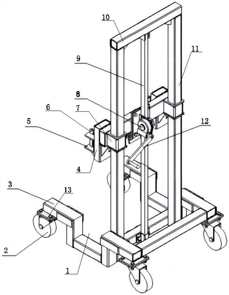
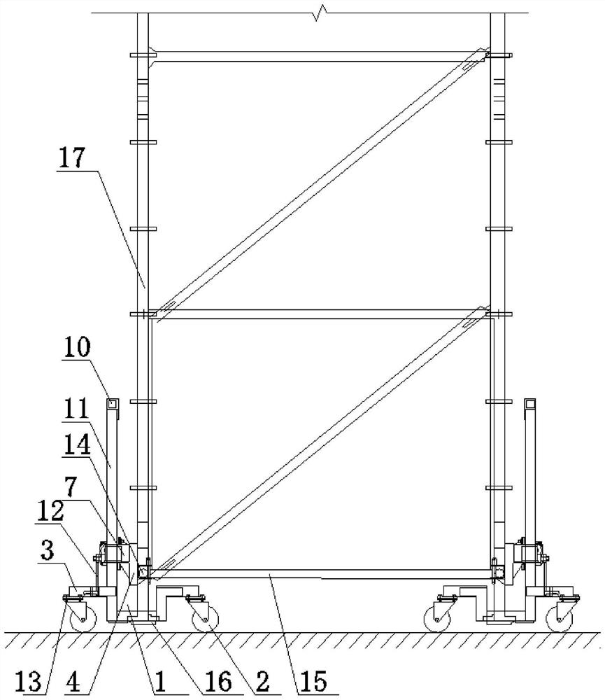
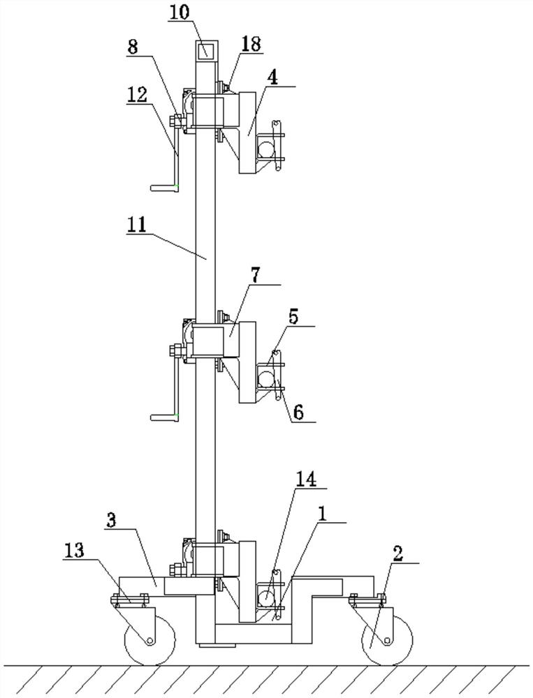
[0032] refer to Figure 1-7, The high-wall scaffolding lifting mobile trolley includes a frame 3, the lower end of the frame 3 is provided with a moving mechanism 2, the upper end of the frame 3 is provided with a pipe beam 10 above the gantry, and the pipe beam 10 above the gantry and the frame 3 are connected There are two symmetrically arranged gantry square tube columns 11, a rack 9 is arranged between the two gantry square tube columns 11, and the two ends of the rack 9 are respectively connected with the frame 3 and the pipe beam 10 above the gantry. Fixed connection, one side of the two gantry square tube columns 11 is provided with ...


PUM


Abstract

The invention discloses a high wall scaffold lifting moving trolley which comprises a trolley frame, a moving mechanism is arranged at the lower end of the trolley frame, a portal upper square tube cross beam is arranged at the upper end of the trolley frame, two symmetrically-arranged portal square tube stand columns are fixedly connected between the portal upper square tube cross beam and the trolley frame, a rack is arranged between the two portal square tube stand columns, and the rack is fixedly connected with the portal upper square tube cross beam. The two ends of the rack are fixedly connected with the frame and the upper pipe cross beam of the portal frame respectively, a movable bracket is arranged on one sides of the two portal frame square pipe stand columns, two scaffold enclasping mechanisms are symmetrically arranged on one side of the movable bracket, and two sliding sleeves are symmetrically arranged at the other end of the movable bracket. According to the high wall scaffold lifting moving trolley and the construction method, the number of steel pipe scaffolds and the scaffold erection cost are reduced, a larger in-site space is provided, various construction costs are reduced, and the high wall scaffold lifting moving trolley has the advantages of being easy and convenient to construct, clear and easy to understand in process procedures and high in operability.

Description

technical field [0001] The invention relates to the technical field of moving continuous high-wall scaffolding, in particular to a lifting and moving trolley for high-wall scaffolding and a construction method. Background technique [0002] In the construction of ultra-high thin-walled walls, the stability of the steel mesh of the wall, the safety of the erection of the supports and the compactness of the concrete vibration have always been the issues that need to be paid attention to in the construction of the thin-walled wall. The wall construction has always been a similar project construction. The main projects in the project, due to the characteristics of high wall height, long length, similar cross-section, and large number of steel bars in the construction of wall engineering, in the construction of commonly used channels and pools, the traditional method is to erect steel pipe scaffolding to meet the requirements of wall steel bar binding. For steel pipe scaffolding ...

Claims


Application Information

Patent Timeline
Patent Type & Authority Applications(China)
IPC IPC(8): E04G1/20E04G1/24E04G5/00E04G5/02E04G5/04E04G5/06
CPCE04G1/20E04G1/24E04G5/00E04G5/007E04G5/02E04G5/04E04G5/061E04G2001/242
Inventor 赵立财
Owner 赵立财
Why Eureka
Eureka Blog
Learn More