
Anti-collision edge band convenient to install

An edge banding and anti-collision technology, which is applied in the directions of transportation and packaging, vehicle safety arrangements, synthetic resin layered products, etc., can solve the problems of not having waterproof and fire prevention, reducing the flexibility and versatility of edge banding, and not having a service life, etc. problems, to achieve good fire and water resistance, good disassembly efficiency, and improve service life

Inactive Publication Date: 2022-07-22
丰县原野塑料科技有限公司
View PDF0 Cites 0 Cited by
  • Summary
  • Abstract
  • Description
  • Claims
  • Application Information

AI Technical Summary

Problems solved by technology

[0003] Edge banding strips are usually installed on electric vehicles. The length of the existing edge banding strips is fixed. In some specific places, multiple sections of edge banding strips are required to be spliced ​​together and then installed. However, the existing technology It is very inconvenient to splice two edge bands, and when one of the edge bands is damaged and needs to be replaced, it is inconvenient to disassemble and replace the damaged edge band, and the existing edge bands are not It has good anti-collision performance. Because electric vehicles are sometimes in many more complicated environments, when the edge banding is subjected to external impact, it is likely to be damaged, and the edge banding does not have the ability to Good corrosion resistance, does not have a good service life, and does not have waterproof and fireproof performance, which reduces the flexibility and versatility of the edge banding

Method used


Image

  • Anti-collision edge band convenient to install
  • Anti-collision edge band convenient to install
  • Anti-collision edge band convenient to install

Examples


Embodiment Construction

[0026] The technical solutions in the embodiments of the present invention will be clearly and completely described below with reference to the accompanying drawings in the embodiments of the present invention. Obviously, the described embodiments are only a part of the embodiments of the present invention, rather than all the embodiments. Based on the embodiments of the present invention, all other embodiments obtained by those of ordinary skill in the art without creative efforts shall fall within the protection scope of the present invention.

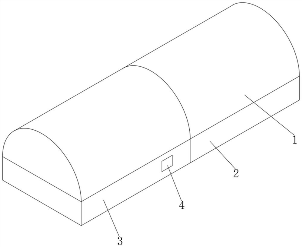
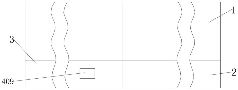
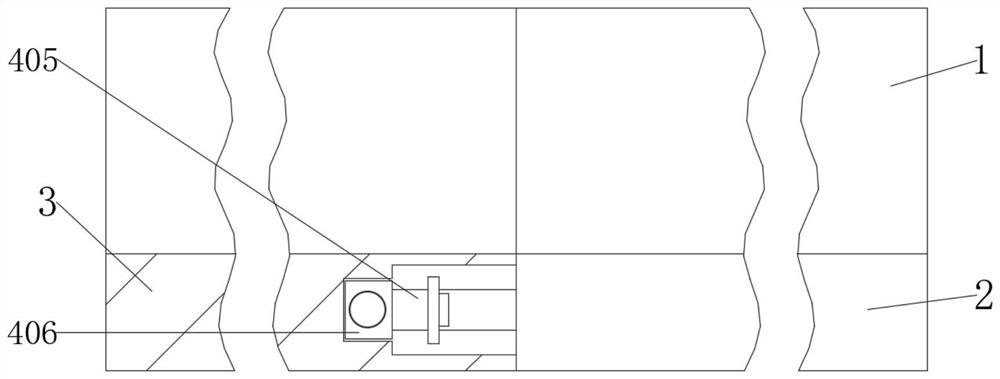
[0027] see Figure 1-6 , the present invention provides a technical solution: comprising an edge strip body 1, the bottom of the edge strip body 1 is respectively fixed with a first connecting plate 2 and a second connecting plate 3, the second connecting plate 3 is provided with a limiting mechanism 4 inside, and the edge sealing The inner side of the strip body 1 is provided with an anti-collision mechanism 5 , the sides of the edg...


PUM


Abstract

The invention discloses a convenient-to-install anti-collision edge band which comprises edge band bodies, the bottom of each edge band body is fixedly connected with a first connecting plate and a second connecting plate, a limiting mechanism is arranged in each second connecting plate, an anti-collision mechanism is arranged on the inner side of each edge band body, and the sides, close to each other, of the edge band bodies make contact with each other. The limiting mechanism comprises a limiting groove, the limiting groove is formed in the right side of the second connecting plate, a connecting rod is fixedly connected to the inner wall of the limiting groove, and the outer wall of the connecting rod is sleeved with a limiting spring. According to the edge sealing strip, through the arranged limiting mechanism, when the two edge sealing strip bodies are spliced, splicing of the two edge sealing strip bodies can be completed only by inserting the connecting blocks into the inserting grooves and then inserting the inserting shafts into the penetrating connecting blocks, good installation efficiency is achieved, and when one of the edge sealing strip bodies is damaged, the two edge sealing strip bodies are not damaged. And the edge sealing strip body can be conveniently detached and replaced, and the good detaching efficiency can be achieved.

Description

technical field [0001] The invention relates to the technical field of edge sealing strips, in particular to an anti-collision edge sealing strip that is easy to install. Background technique [0002] The main component of pvc edge banding is polyvinyl chloride, which is made by mixing, calendering, vacuum forming and other processes. The products are widely used in furniture, office, kitchen utensils, teaching equipment, civil laboratories, etc. The thickness is from 0.3 to 3mm, and the width is from 12mm to 80mm. , The surface and back are flat, the thickness is uniform, the width is consistent, the hardness is reasonable, the elasticity is high, the quality is good, and the wear resistance is strong. coordination. [0003] Edge strips are usually installed on electric vehicles. The length of the existing edge strips is fixed. In some specific places, multiple sections of edge strips need to be spliced ​​together and then installed. However, the existing technology It i...

Claims


Application Information

Patent Timeline
IPC IPC(8): B60R13/04B60R19/00B32B9/00B32B9/04B32B27/12B32B27/28B32B27/32B32B25/08B32B25/16
CPCB60R13/04B60R19/00B32B9/00B32B9/04B32B27/12B32B27/28B32B27/322B32B25/08B32B25/16
Inventor 程彬
Owner 丰县原野塑料科技有限公司
Learn More