Flushing device for cataract cornea
A technology for flushing device and cataract, applied in bathing device, physical therapy, ophthalmic surgery, etc., can solve the problem of inability to flush the cornea, and achieve the effect of improving practicability and reducing consumption.
- Summary
- Abstract
- Description
- Claims
- Application Information
AI Technical Summary
Problems solved by technology
Method used
Image

Examples
Embodiment 1
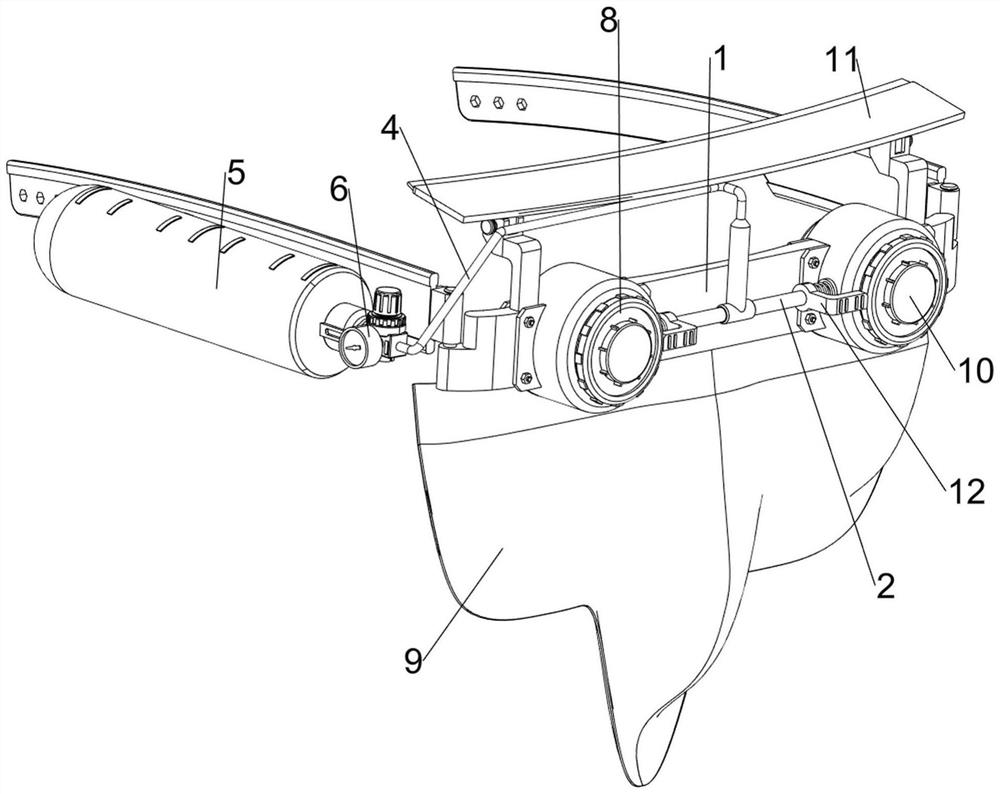
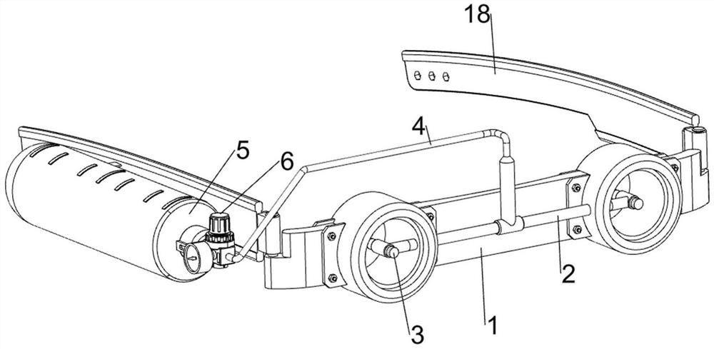
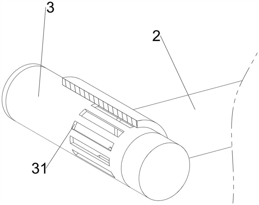
[0035] A device for irrigating the cornea for cataracts, please see Figure 1-7 , including glasses frame 1, glasses legs 18, connecting pipe 2, sliding pipe 3, fixed pipe 4, water tank 5, water pump 6, flushing mechanism 7 and rotating mechanism 8, and the left and right sides of the glasses frame 1 are rotatably connected with glasses Leg 18, the front side of the spectacle frame 1 is connected with a connecting tube 2, the left and right sides of the connecting tube 2 are both rotated and connected with a sliding tube 3, and the two sliding tubes 3 are evenly spaced with elongated holes 31, The left side of the left temple 18 is connected with the water tank 5 by welding, the rear side of the water tank 5 is screwed and connected with a cover, the front side of the water tank 5 is installed with a water pump 6, the water pump 6 is connected with the water tank 5, and the outlet of the water pump 6 is connected. A fixed pipe 4 is connected between the water pipe and the conn...
Embodiment 2
[0040] On the basis of Example 1, please see figure 1 and Figure 8 , also includes a liquid suction mechanism 9, the liquid suction mechanism 9 includes a mask 91, a sponge strip 92 and a fixing block 93, the lower side of the spectacle frame 1 is connected with a mask 91, and the rear side of the upper part of the mask 91 is connected with a sponge strip 92, sponge The top of the bar 92 is connected with two fixing blocks 93, and the two fixing blocks 93 are symmetrical on the left and right.
[0041] When the device needs to be used, the two temples 18 are respectively worn on the patient's ears in a manner of simulating wearing glasses, at this time, the two fixing blocks 93 will be in contact with the patient's nasion, thereby increasing the wear resistance of the device. Stability, and the sponge strip 92 will be in contact with the patient's face at this time, and then when rinsing the eyes, the flushing liquid flowing from the eyes can be absorbed by the sponge strip ...
Embodiment 3
[0043] On the basis of Example 2, please see figure 1 , Figure 9 , Figure 10 and Figure 11 , also includes a nozzle adjustment mechanism 10, the nozzle adjustment mechanism 10 includes a sliding block 101, a first return spring 102, a third connecting block 103, a connecting rod 104, a magnet 105, a guide rod 106, an iron block 107 and a slider 108, The front sides of the two rotating frames 82 are slidably connected with sliding blocks 101 , the two sliding blocks 101 are connected with the adjacent first connecting blocks 81 , and the two sliding blocks 101 are connected with the adjacent rotating frames 82 . There is a first return spring 102, a third connecting block 103 is connected to the bottom rear sides of the two sliding tubes 3, and guide rods 106 are connected to the lower sides of the two guide frames 72 by welding, and the two guide rods 106 slide on both. The sliders 108 are connected in a rotatable manner, the rear upper sides of the two sliders 108 are c...
PUM
 Abstract
Description
Claims
Application Information
 - Generate Ideas
- Intellectual Property
- Life Sciences
- Materials
- Tech Scout
- Unparalleled Data Quality
- Higher Quality Content
- 60% Fewer Hallucinations
Browse by: Latest US Patents, China's latest patents, Technical Efficacy Thesaurus, Application Domain, Technology Topic, Popular Technical Reports.
© 2025 PatSnap. All rights reserved.Legal|Privacy policy|Modern Slavery Act Transparency Statement|Sitemap|About US| Contact US: help@patsnap.com