Backlight module and display device
A kind of backlight module, technology of display device
- Summary
- Abstract
- Description
- Claims
- Application Information
AI Technical Summary
Problems solved by technology
Method used
Image

Examples
no. 1 example
[0027] A first aspect of the present application provides a backlight module. The backlight module includes a backplane, at least two lamp boards, a diffuser plate, and a multilayer optical film. The at least two lamp boards are disposed on one side of the backplane, and the diffuser plate is disposed On the side of the light plate away from the back plate, the multilayer optical film is arranged on the side of the diffuser plate away from the light plate. The backlight module further includes at least two magnetic attraction parts, the magnetic attraction parts are arranged on one side of the lamp panel, and the lamp panel is magnetically attracted to one side of the back panel through the magnetic attraction parts.
[0028] Wherein, the back panel has a light panel installation side and a back side, the light panel installation side is used for installing the light panel, and the back side of the back panel and the light panel installation side of the back panel are opposite ...
no. 2 example
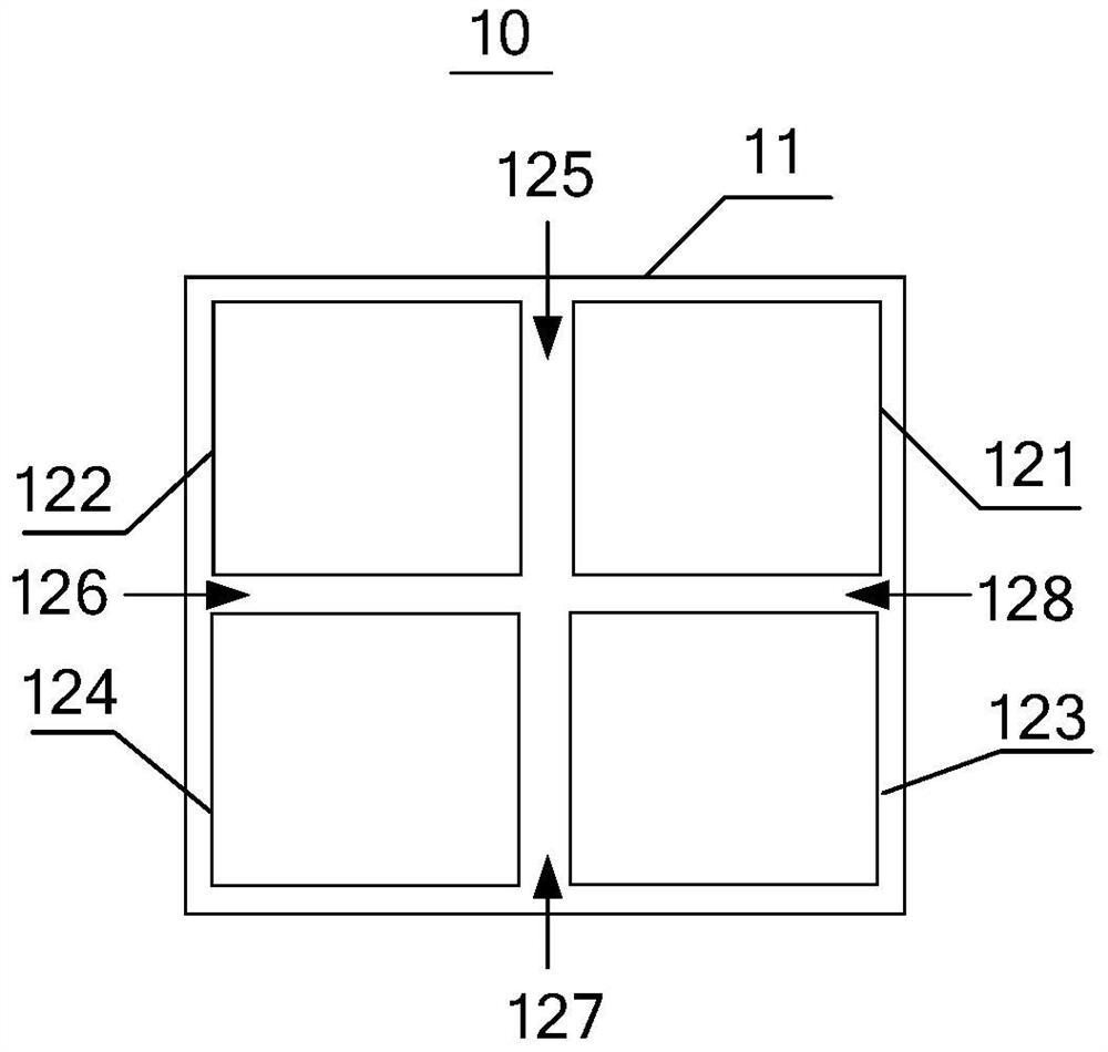
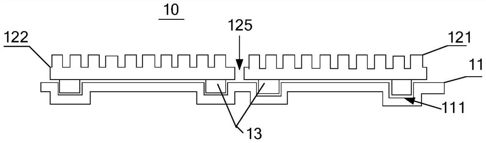
[0042] see image 3 , image 3 It is a schematic structural diagram of the backlight module 10 provided by the second embodiment of the present application. The backlight module 10 provided in the second embodiment is based on the first embodiment, and related content can be found in the above-mentioned first embodiment.
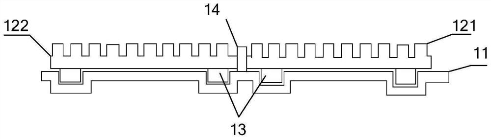
[0043] Specifically, in the above-mentioned group provided with opposite magnetic poles: the reflective paste 14 is provided at the spaced position between the first lamp board 121 and the second lamp board 122 , and the reflective paste 14 is protruded relative to the upper surface of the lamp board. . Wherein, the upper surface of the lamp board is the surface away from the backplane and provided with the lamp beads. Combined with the content of the above-mentioned embodiment, that is, the reflective paste 14 is provided at the first joint 125 , and the reflective paste 14 is protruded from the upper surfaces of the first lamp board 121 and the second l...
no. 3 example
[0076] Another aspect of the present application provides a display device 20, please refer to Image 6 , Image 6 It is a schematic structural diagram of the display device 20 provided by the third embodiment of the present application.
[0077] Specifically, the display device 20 may include a backlight module and a display panel 21, and the backlight module may be the backlight module 10 described in any of the above embodiments, and the backlight module 10 is disposed on the non-display side of the display panel 21, and then The backlight module 10 is used to provide a backlight source for the display panel 21 so that the display panel 21 can display.
PUM
 Abstract
Description
Claims
Application Information
 - R&D
- Intellectual Property
- Life Sciences
- Materials
- Tech Scout
- Unparalleled Data Quality
- Higher Quality Content
- 60% Fewer Hallucinations
Browse by: Latest US Patents, China's latest patents, Technical Efficacy Thesaurus, Application Domain, Technology Topic, Popular Technical Reports.
© 2025 PatSnap. All rights reserved.Legal|Privacy policy|Modern Slavery Act Transparency Statement|Sitemap|About US| Contact US: help@patsnap.com