Disposable blood pressure collection device, analysis system and real-time blood pressure collection method
A collection device and a one-time technology, which can be applied to parts of connection devices, coupling devices, medical/surgical connectors, etc., can solve the problems of inconvenient installation, inconvenient assembly, and non-detachability of PIN connectors, achieving detachable settings, Ease of assembly and improved airtightness
- Summary
- Abstract
- Description
- Claims
- Application Information
AI Technical Summary
Problems solved by technology
Method used
Image

Examples
Embodiment 1
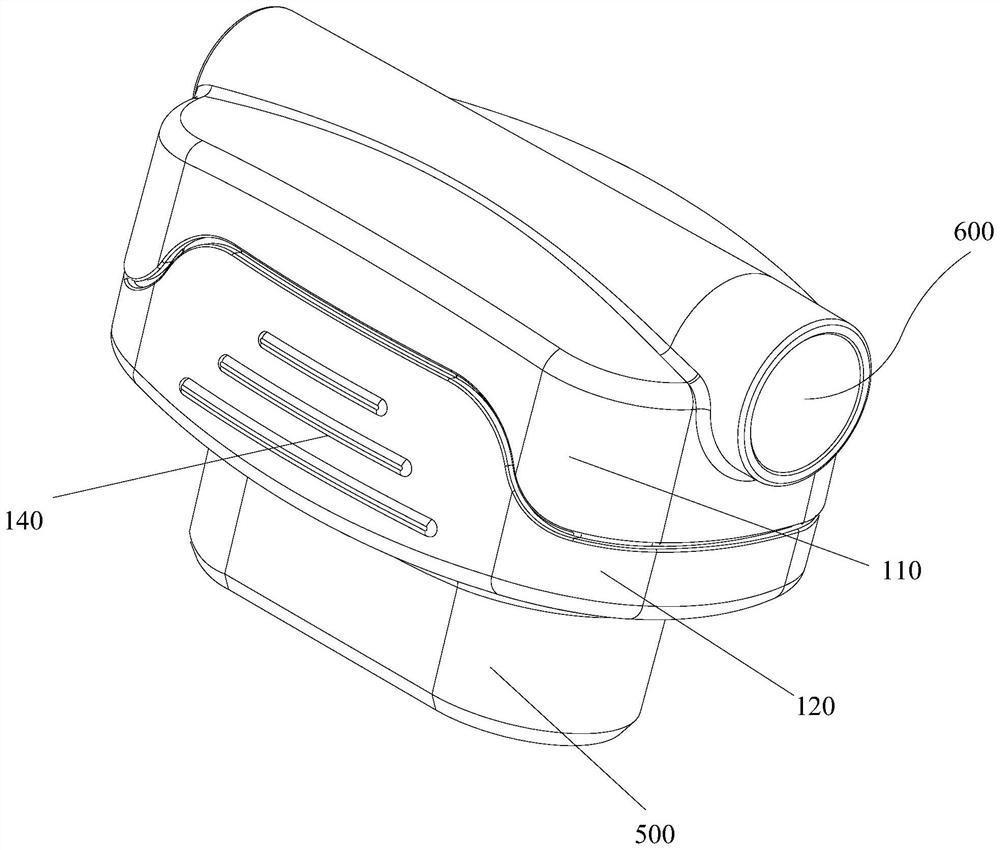
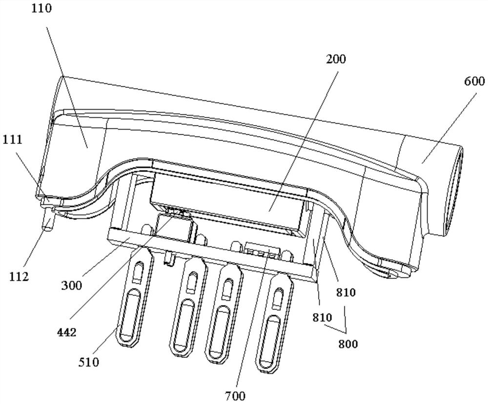
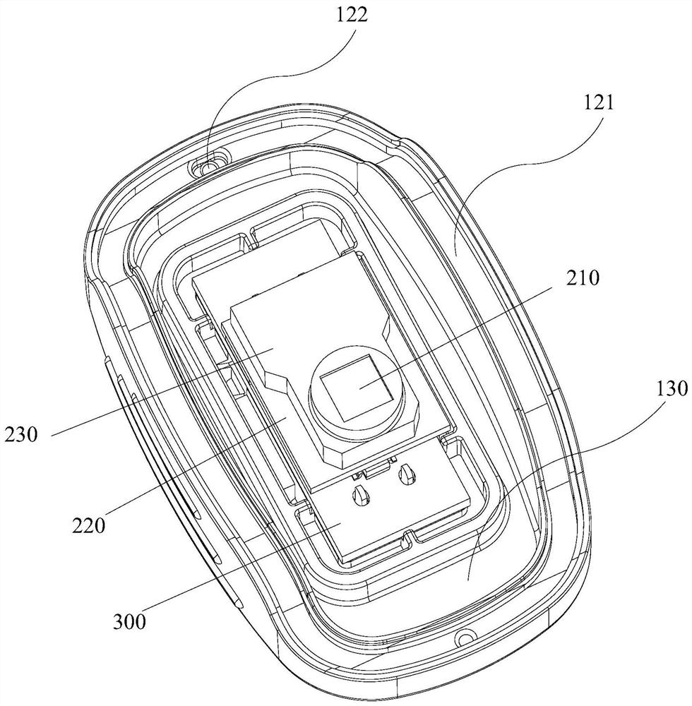
[0055] like figure 1 and figure 2 and image 3 As shown, in order to achieve the above purpose, the present application provides a disposable blood pressure collection device, including: a housing 100, an integrated circuit board 300, a blood pressure sensor 200, a PIN connector 400, a first connection structure 500 and a through tube 600; The blood pressure sensor 200, the integrated circuit board 300, and the PIN connector 400 are all arranged in the casing 100; the blood pressure sensor 200 is connected to the integrated circuit board 300 through the PIN connector 400; the first connection structure 500 is respectively connected to the casing 100, the integrated circuit The plate 300 is connected to the outside to transmit the pressure value collected by the blood pressure sensor 200; away from the direction of the first connecting structure 500, the through pipe 600 is arranged on the top of the housing 100, and the inner surface of the through pipe 600 is provided with ...
Embodiment 2
[0059] On the basis of Example 1, in one embodiment of the present application, such as Image 6 As shown, the signal transmission mechanism 420 includes such as Figure 9 SMT patch 421 shown and as Image 6 The first pogo pin 422 shown, the SMT patch 421 is arranged in the middle position of the body 410, one end of the SMT patch 421 is attached to the body 410, and each SMT patch 421 attached to the body 410 is connected to a first spring The ends of the needle 422 are connected, the first pogo pin 422 passes through the body 410, and the other end of the first pogo pin 422 is exposed outside the body 410; it is connected to the other end of the blood pressure sensor 200 for receiving and transmitting the blood pressure sensor 200. Pressure value; set on the body 410 such as Figure 4 As shown in the first connecting unit 411, the gripping mechanism 430 is set as Figure 4 The second connection unit 431 is shown, and the first connection unit 411 is connected to the secon...
Embodiment 3
[0067] like figure 1 and image 3 As shown, on the basis of Embodiment 1, in an embodiment of the present application, the interior of the housing 100 is set as figure 2 The cavity 130 shown includes an upper shell 110 and a lower shell 120 , and the upper shell 110 is connected to the lower shell 120 . In the present application, the housing 100 is divided into upper and lower housings to facilitate the installation of the internal structure of the housing 100 . In this application, the blood pressure sensor 200 and the PIN connector 400 are arranged in the cavity 130 of the housing 100 as a closed structure, which improves the sealing effect, has a high degree of integration, reduces the volume, and has a neat and beautiful appearance.
[0068] The blood pressure sensors 200 used in this application are generally kept manually, and the used and unused blood pressure sensors 200 are placed separately. It can be seen that there are errors in manual storage, and the problem...
PUM
 Abstract
Description
Claims
Application Information
 - R&D
- Intellectual Property
- Life Sciences
- Materials
- Tech Scout
- Unparalleled Data Quality
- Higher Quality Content
- 60% Fewer Hallucinations
Browse by: Latest US Patents, China's latest patents, Technical Efficacy Thesaurus, Application Domain, Technology Topic, Popular Technical Reports.
© 2025 PatSnap. All rights reserved.Legal|Privacy policy|Modern Slavery Act Transparency Statement|Sitemap|About US| Contact US: help@patsnap.com