
Anti-disassembly bounce-off type beacon locking and releasing device

A locking-release and pop-up technology, applied in the direction of fixtures, machines/brackets, supporting machines, etc., can solve the problems of low locking and releasing reliability, false triggering and false releasing of beacons, complicated structure, etc., to avoid Electronic interference, improved reliability, small size effect

Pending Publication Date: 2022-07-12
CETC NINGBO MARINE ELECTRONICS RES INST
View PDF0 Cites 0 Cited by
  • Summary
  • Abstract
  • Description
  • Claims
  • Application Information

AI Technical Summary

Problems solved by technology

[0003] The lock release device of the existing beacon is mainly divided into an electronic control lock release device and a mechanical lock release device; no matter what type of lock release device, there are certain problems, specifically, the existing electronic control lock The tight release device is susceptible to interference from the surrounding electromagnetic environment, especially if there are high-power transmitting equipment around, such as radar. When the high-power transmitting equipment is running, it often causes the beacon to be accidentally triggered and released by the electronically controlled locking and releasing device, resulting in locking. Low reliability of release;
[0004] Although the existing mechanical lock release device will not be disturbed by the surrounding electromagnetic environment, the existing mechanical lock release device also uses a steering gear and a transfer structure inside, and the structure is complex, resulting in a larger overall volume

Method used


Image

  • Anti-disassembly bounce-off type beacon locking and releasing device
  • Anti-disassembly bounce-off type beacon locking and releasing device
  • Anti-disassembly bounce-off type beacon locking and releasing device

Examples


Embodiment Construction

[0042] The following is further described in detail by specific embodiments:

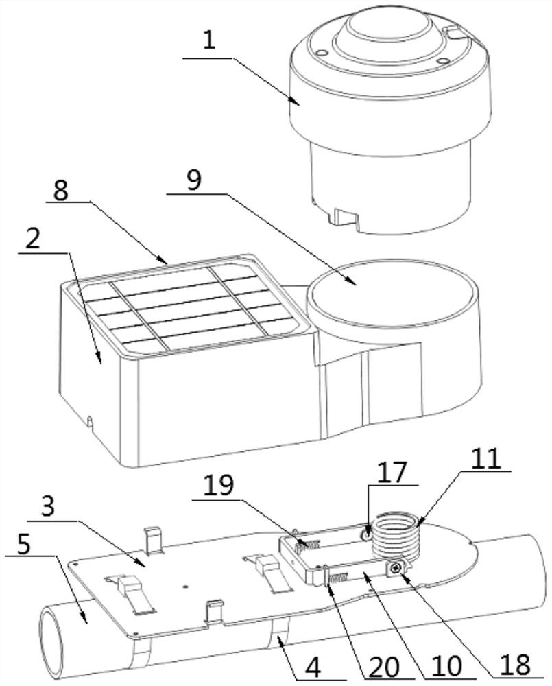
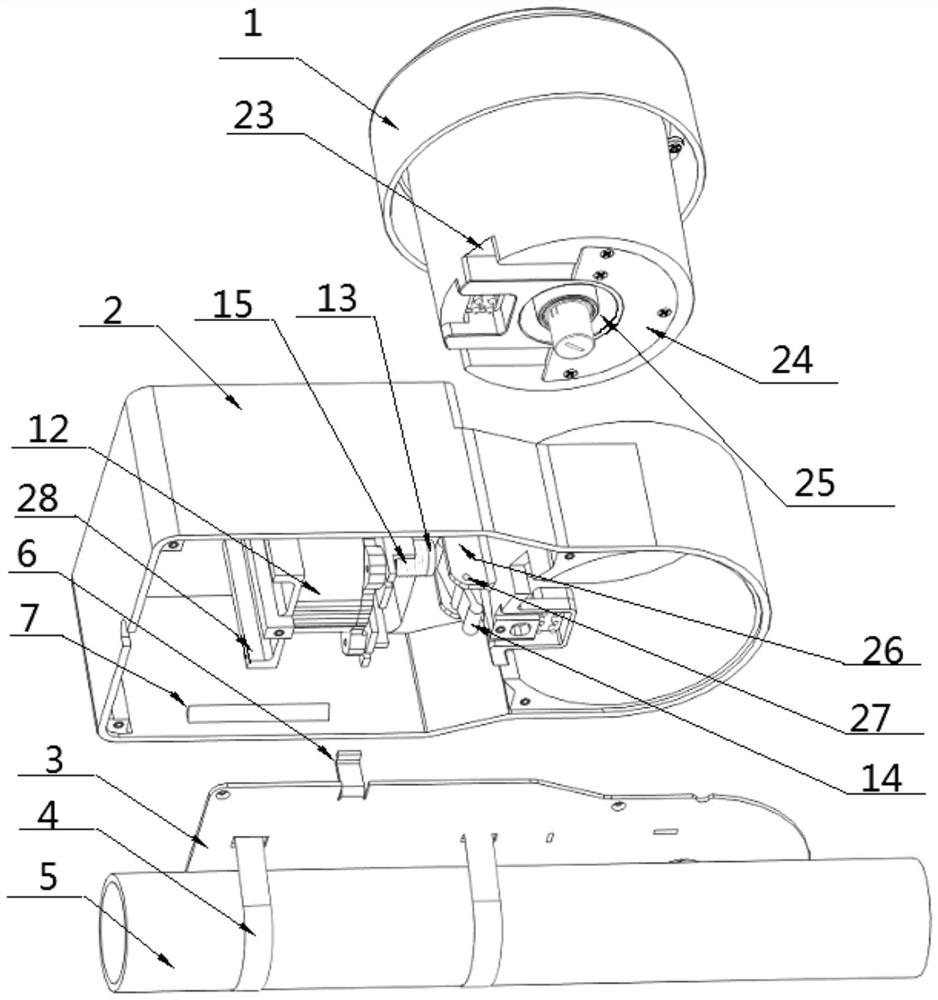
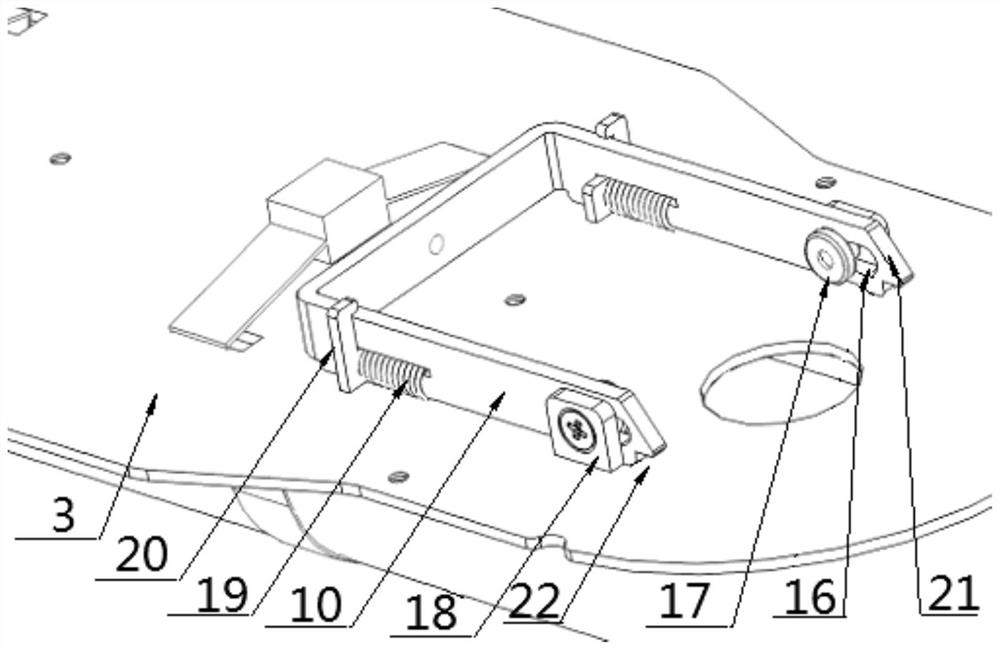
[0043] The reference signs in the drawings include: beacon 1, shell 2, base 3, throat hoop 4, fence 5, barb buckle 6, clamping block 7, solar charging device 8, beacon mounting hole 9, U Type lock tongue 10, beacon spring 11, hydrostatic pressure release 12, push rod 13, lever lever 14, push rod spring 15, limit hole 16, limit pin 17, baffle 18, U-shaped lock Tongue spring 19 , limit plate 20 , inclined surface 21 , cut angle 22 , U-shaped groove 23 , buckle plate 24 , annular groove 25 , support lug 26 , pin shaft 27 , mounting piece 28 .

[0044] The example is basically as attached figure 1Shown: An anti-disassembly pop-open locking and releasing beacon 1 device for locking and releasing the beacon 1, including: a casing 2, a base 3, a throat hoop 4 and a locking and releasing mechanism; the locking and releasing mechanism part Set on the base 3, partly on the inner wall of the shell 2, the she...


PUM


Abstract

The invention relates to the technical field of help seeking equipment, in particular to an anti-disassembly pop-up type beacon locking and releasing device which is used for locking and releasing a beacon and comprises a base and a locking and releasing mechanism. The locking and releasing mechanism comprises a U-shaped spring bolt, a beacon spring, a hydrostatic pressure releaser, a push rod and a lever type deflector rod; the U-shaped spring bolt is connected with the base in a sliding mode, and the opening end of the U-shaped spring bolt is used for being connected with a beacon in a clamping mode; the beacon spring is arranged at the opening end of the U-shaped spring bolt, the lever type deflector rod is arranged at the other end of the U-shaped spring bolt, one end of the lever type deflector rod makes contact with the U-shaped spring bolt, the other end of the lever type deflector rod makes contact with one end of the push rod, the other end of the push rod is connected with the hydrostatic pressure releaser, and the push rod is sleeved with the push rod spring. According to the scheme, locking and releasing of the beacon are completed through ingenious connection of pure mechanical devices, the structure is simple, the size is small, external electronic interference can be effectively avoided, and reliability is improved.

Description

technical field [0001] The invention relates to the technical field of rescue equipment, in particular to an anti-disassembly and pop-open locking and releasing beacon device. Background technique [0002] As a rescue device, beacons have a wide range of applications, especially in related fields of marine operations. By locking the beacon on the corresponding object, in the event of danger, the beacon is triggered to escape, and the rescue positioning is carried out, and the rescue personnel are guided to carry out the search and rescue work in time, which greatly improves the rescue success rate. [0003] The locking and releasing devices of existing beacons are mainly divided into electronically controlled locking and releasing devices and mechanical locking and releasing devices; no matter which type of locking and releasing device it is, there are certain problems. Specifically, the existing electronically controlled locking and releasing devices The tight release devi...

Claims


Application Information

Patent Timeline
Patent Type & Authority Applications(China)
IPC IPC(8): F16M11/04F16M13/02F16B1/00
CPCF16M11/041F16M13/02F16B2200/89
Inventor 陈海民陈建林姚克波罗新林黄毫军张群峰王兵骆曹飞徐深洋
Owner CETC NINGBO MARINE ELECTRONICS RES INST
Learn More