Polishing machine for automobile engine crankshaft

A technology for automobile engines and polishing machines, which is applied to surface polishing machine tools, grinding/polishing equipment, grinding racks, etc. It can solve the problems of inability to complete fast polishing at one time, incomplete control of precision, and low efficiency of manual polishing, etc. Problems, to achieve the effect of polishing is not easy to deform, improve efficiency, and ensure polishing accuracy

Pending Publication Date: 2022-07-12
杜晨晨
View PDF8 Cites 1 Cited by
  • Summary
  • Abstract
  • Description
  • Claims
  • Application Information

AI Technical Summary

Problems solved by technology

[0003] For the existing technology, crankshaft polishing often requires multiple steps, and rapid polishing cannot be completed at one time. The use of polishing machines is of great significance in production.
However, the traditional process is time-consuming and labor-intensive, the efficiency of manual polishing is low, the precision cannot be completely controlled, and the phenomenon of workpiece scrapping is very easy to occur, so a device to solve the above problems is needed

Method used


Image

  • Polishing machine for automobile engine crankshaft
  • Polishing machine for automobile engine crankshaft
  • Polishing machine for automobile engine crankshaft

Examples


Embodiment Construction

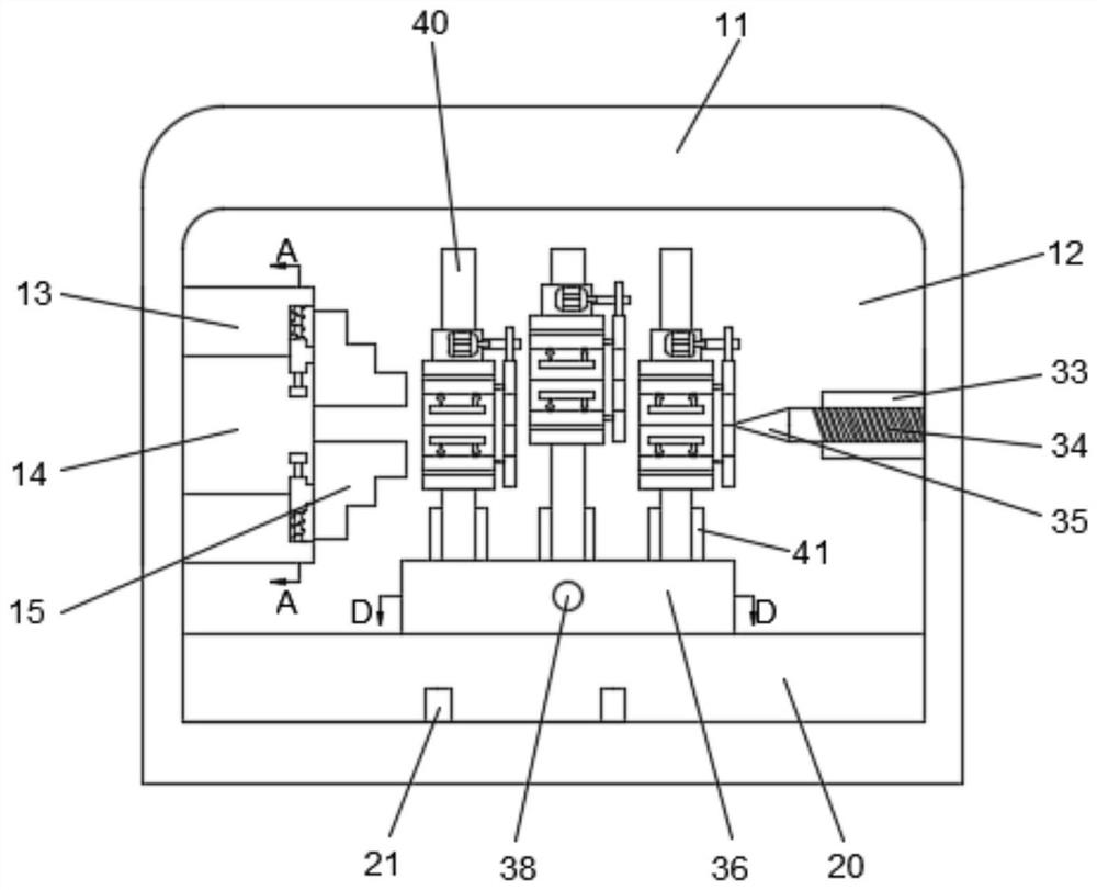
[0028] In the description of the present invention, it should be understood that the terms "upper", "lower", "front", "rear", "left", "right", "vertical", "horizontal", "top", The orientation or positional relationship indicated by "bottom", "inside", "outside", etc. is based on the attached figure 2 The orientation or positional relationship shown is only a simplified description for the convenience of describing the present invention, rather than indicating or implying that the indicated device or element must have a specific orientation, be constructed and operated in a specific orientation, and therefore should not be construed as a reference to the present invention. limits:

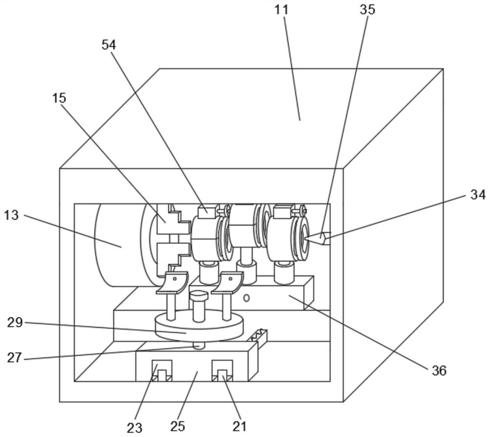
[0029] Refer to the attached Figure 1-Figure 8 , according to an embodiment of the present invention, an automobile engine crankshaft polishing machine includes a main box body 11, a polishing cavity 12 is arranged in the main box body 11, and a telescopic clamping column is arranged on the left ...


PUM


Abstract

The invention relates to the technical field of crankshaft polishing, in particular to an automobile engine crankshaft polishing machine which comprises a main box body, a polishing cavity is formed in the main box body, a telescopic clamping column is arranged on the left wall in the polishing cavity, a clamping cavity is formed in the telescopic clamping column, and a clamping table is fixedly arranged on the right end face of the telescopic clamping column. Displacement grooves which are provided with rightward openings and are evenly distributed are formed in the right side of the telescopic clamping column, fixing rods are fixedly arranged on the side walls, away from the clamping cavity, of the displacement grooves, telescopic springs capable of stretching out and drawing back are arranged on the outer circle faces of the fixing rods, and guiding sliding rails which are symmetrical left and right are fixedly arranged on the lower wall of the front side of the polishing cavity. The placing plate is fixedly arranged in the fixing shell, the friction shaft is rotationally arranged in the placing plate, the friction cavity is formed in the friction shaft, the contact shell is fixedly arranged on the side, away from the circle center of the fixing shell, of the friction cavity, the friction block makes contact with the crankshaft, rotating polishing is driven through rotation of the motor, efficiency is improved, polishing is uniform, and deformation is not likely to happen.

Description

technical field [0001] The invention relates to the technical field of crankshaft polishing, in particular to an automobile engine crankshaft polishing machine. Background technique [0002] The engine crankshaft is an important part in the engine, and its processing requirements are more complicated. It bears the force from the connecting rod and converts it into torque, which is output through the crankshaft and drives other accessories on the engine to work. Therefore, the crankshaft needs sufficient strength and rigidity. , The surface of the journal needs to be wear-resistant and other characteristics. [0003] For the prior art, crankshaft polishing often requires multiple steps, and rapid polishing cannot be completed at one time. The use of polishing machines is extremely important in production. However, the traditional process is time-consuming and labor-intensive, the manual polishing efficiency is low, the precision cannot be completely controlled, and the pheno...

Claims


Application Information

Patent Timeline
Patent Type & Authority Applications(China)
IPC IPC(8): B24B29/02B24B41/02B24B41/04B24B41/06B24B47/12B24B47/22
CPCB24B29/02B24B41/067B24B47/22B24B41/02B24B41/04B24B47/12
Inventor 杜晨晨
Owner 杜晨晨
Why Eureka
Try Eureka