
Intelligent controllable maintenance-free dehumidification device and dehumidification method thereof

A maintenance-free, intelligent technology, applied in separation methods, chemical instruments and methods, and separation of dispersed particles, can solve problems such as increasing the daily maintenance workload of operation and maintenance personnel, damaging equipment in the cabinet, and reducing humidity in the cabinet. Improve work independence, avoid manual intervention, and have strong environmental adaptability

Pending Publication Date: 2022-07-12
YANTAI POWER SUPPLY COMPANY OF STATE GRID SHANDONG ELECTRIC POWER
View PDF2 Cites 0 Cited by
  • Summary
  • Abstract
  • Description
  • Claims
  • Application Information

AI Technical Summary

Problems solved by technology

However, due to the poor air circulation in the cabinet, this dehumidification method cannot fundamentally reduce the humidity in the cabinet, and the high-humidity air will still damage the equipment in the cabinet
However, the use of adsorption dehumidification devices requires regular replacement of the adsorbent, which not only increases the cost, but also increases the daily maintenance workload of the operation and maintenance personnel. Therefore, it is necessary to develop an intelligent controllable maintenance-free dehumidification device, which can fundamentally eliminate The air moisture in the cabinet reduces the humidity in the cabinet and does not require regular maintenance

Method used


Image

  • Intelligent controllable maintenance-free dehumidification device and dehumidification method thereof
  • Intelligent controllable maintenance-free dehumidification device and dehumidification method thereof

Examples


Embodiment 1

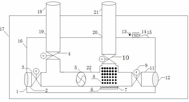
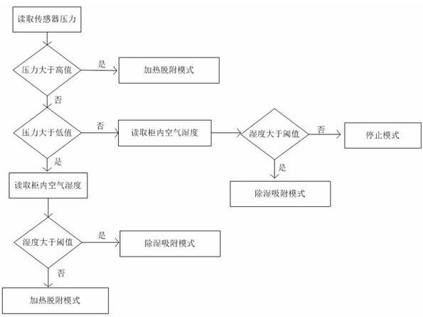
[0031] An intelligent controllable maintenance-free dehumidification device of this embodiment, refer to the appendix Figure 1-2 , including the device housing 16 installed in the mechanism box cabinet 17, and the device housing 16 is equipped with a dehumidification intake pipe 2, a desorption intake pipe 19, a desorption exhaust pipe 20, and a dehumidification exhaust pipe 11, wherein the dehumidification intake pipe is installed. 2 and the dehumidification exhaust pipe 11 are communicated with each other through the intermediate pipe 22 and the three are on the same straight line. The intermediate pipe 22 is equipped with an exhaust fan 5 and partially placed with an adsorbent 8, and the outlet end of the desorption intake pipe 19 is connected to the middle. The pipe 22 is connected, the inlet end extends to the outside of the mechanism box body 17, the inlet end of the desorption exhaust pipe 20 is communicated with the intermediate pipe 22, the outlet end extends to the o...


PUM


Abstract

The invention relates to an intelligent controllable maintenance-free dehumidification device and a dehumidification method thereof, and belongs to the technical field of power transformation operation and maintenance of a power system. Comprising a device shell installed in a mechanism box cabinet body, a dehumidification air inlet pipe, a desorption air inlet pipe, a desorption exhaust pipe and a dehumidification exhaust pipe are installed in the device shell, the dehumidification air inlet pipe and the dehumidification exhaust pipe are communicated through a middle pipe, an adsorbent is placed in the middle pipe, one end of the dehumidification air inlet pipe is provided with a dehumidification air inlet and a dehumidification air inlet valve, and the other end of the dehumidification air inlet pipe is provided with a dehumidification air outlet. A dehumidification air inlet and a dehumidification exhaust valve are arranged at one end of the dehumidification air inlet pipe, the dehumidification air inlet extends to the outside of the device shell, a dehumidification exhaust port and a dehumidification exhaust valve are arranged at one end of the dehumidification exhaust pipe, the dehumidification exhaust port extends to the outside of the device shell, a desorption air inlet valve is mounted on the desorption air inlet pipe, a desorption exhaust valve is mounted on the desorption exhaust pipe, and all the valves are controlled by a controller. By setting a control strategy, multiple working modes can be switched, multiple functions of moisture adsorption, dehumidizer desorption, automatic start and stop and the like are achieved, and meanwhile the device is small in size, convenient to carry and capable of being placed and used at any time.

Description

technical field [0001] The invention relates to an intelligent controllable maintenance-free dehumidification device and a dehumidification method thereof, which are widely used in the dehumidification and maintenance process of narrow and confined spaces such as terminal boxes, mechanism boxes and control cabinets in substations, and belong to the technical field of power system substation operation and maintenance. . Background technique [0002] At present, there are many terminal boxes and mechanism boxes in substations that are exposed to the outdoor air. When the weather conditions such as rain and cold wave occur, the terminal box will increase the air humidity in the cabinet due to the reasons such as the cabinet door is not tightly closed and the temperature difference between inside and outside the cabinet is large. Condensation may cause corrosion of wiring terminals in the cabinet, short circuit of relay contacts, etc., thus affecting the normal operation of the ...

Claims


Application Information

Patent Timeline
Patent Type & Authority Applications(China)
IPC IPC(8): B01D53/26
CPCB01D53/261
Inventor 王宝栋李现忠李元飞司新跃刘志洋徐强于慎航梁欢杨涛朱天宇韩日东王天一苗晓峰李国辉李治一王佳霖尹霖
Owner YANTAI POWER SUPPLY COMPANY OF STATE GRID SHANDONG ELECTRIC POWER
Learn More