Blood collection device for hemodialysis nursing
A technology of blood collection and hemodialysis, which is applied in the medical field, can solve problems that affect the accuracy of blood testing, the clamping device cannot be satisfied, and the outer wall of the blood collection tube is easy to absorb bacteria, so as to save energy, prevent blood coagulation, and avoid pollution. Effect
- Summary
- Abstract
- Description
- Claims
- Application Information
AI Technical Summary
Problems solved by technology
Method used
Image
Examples
Embodiment 1
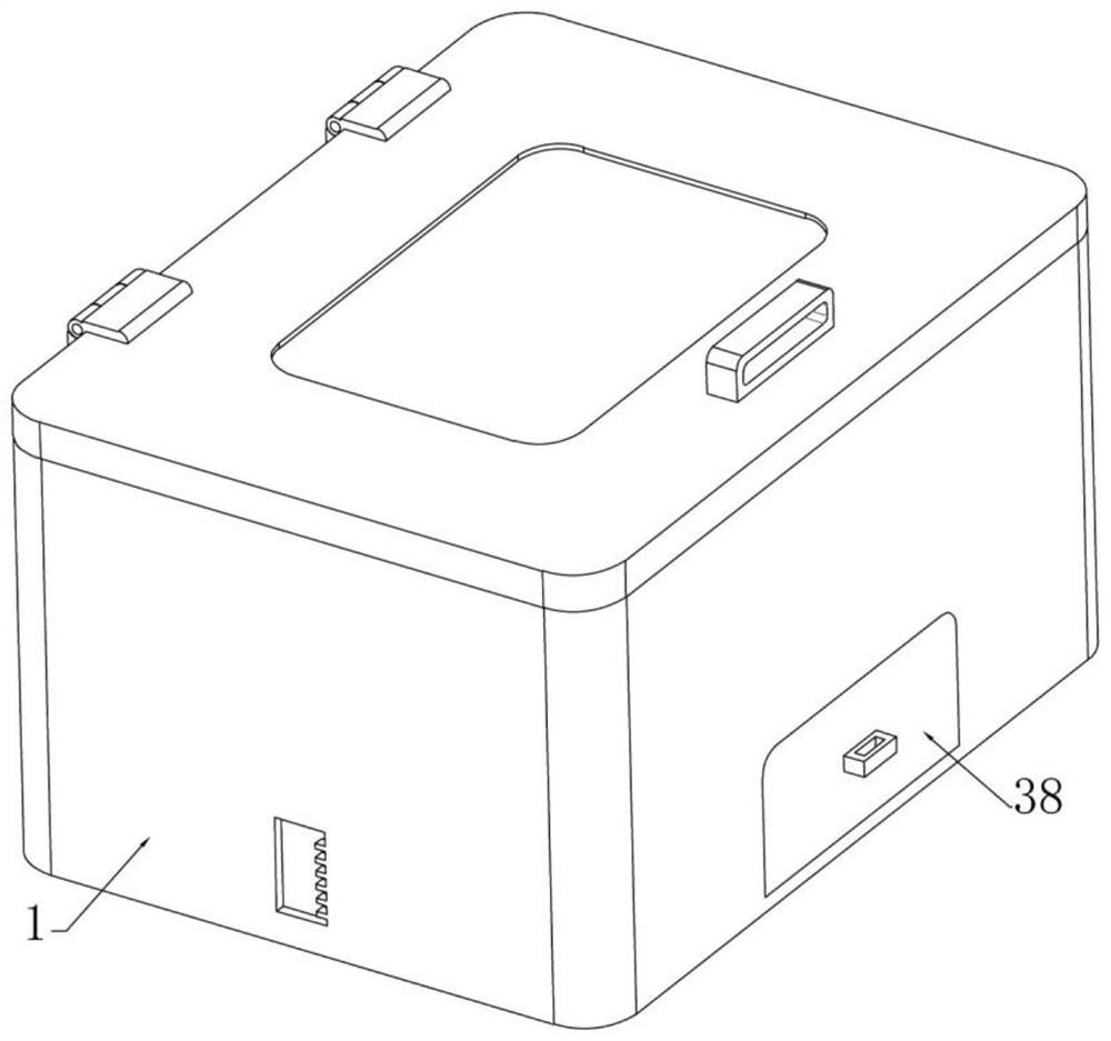
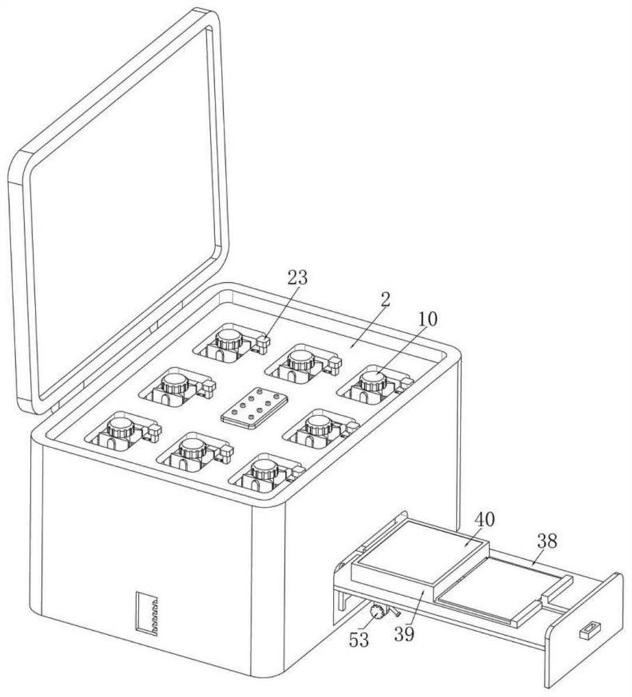
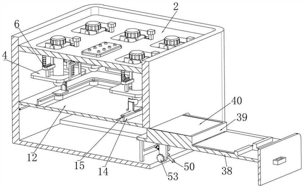
[0042] Example one, as Figure 1-17As shown, a blood collection device for hemodialysis nursing includes a collection box 1, the upper end of the collection box 1 is rotatably installed with a box cover, and the box cover can be closed or opened during use, and the upper end of the inner side of the collection box 1 is fixed A positioning plate 2 is installed. The positioning plate 2 is provided with a plurality of swing holes 3 that are close to the side walls around the collection box 1. Each swing hole 3 is a rectangular structure. A lift plate ring 4 below each swing hole 3, each of the lift plate rings 4 is respectively provided with a circular hole that penetrates up and down, and each of the lift plate rings 4 is respectively fixed with supports at both ends of the circular hole Column 5, each of the support columns 5 is respectively fixed with a guide block 6, the upper end of each of the guide blocks 6 is respectively provided with a guide groove, the guide block 6 ca...
Embodiment 2
[0045] Embodiment 2, on the basis of Embodiment 1, as Image 6 As shown, a fixing plate 12 located under each collecting tube 10 is fixedly installed in the collecting box 1, and a plurality of driving pulleys 13 are respectively rotatably installed at the four corners of the upper end of the fixing plate 12. An active conveyor belt 14 is installed between 13, the upper end of the active conveyor belt 14 is fixedly installed with a flexible belt 15, the flexible belt 15 can rotate with the active transmission belt 14, and the upper end of the flexible belt 15 is fixedly installed with a plurality of Auxiliary plates 16, the upper end of each auxiliary plate 16 is respectively fixed with a vertical push plate 17, each of the vertical push plates 17 is respectively fixed with an arc-shaped push plate 18, and each of the arc-shaped push plates 18 The openings are the same, the upper end of each arc-shaped push plate 18 is close to the bottom of each lifting plate ring 4, and does...
Embodiment 3
[0047] Embodiment 3, on the basis of Embodiment 1, as Figure 8 and Figure 11 As shown, a telescopic rod 19 is installed between each of the lifting plate ring 4 and the positioning plate 2, and a telescopic spring 20 is sleeved on each of the telescopic rods 19, and one end of each of the telescopic springs 20 is fixed It is connected to the lifting plate ring 4, and the other end is fixedly connected to the lifting plate ring 4. In the initial state, each telescopic rod 19 is in a retracted state, and a frame body 21 is fixedly installed on each of the lifting plate rings 4. , a convex body 22 is fixedly installed on each of the box bodies 21, a sliding hole located above each convex body 22 is respectively opened on the positioning plate 2, and a sliding hole is slidably installed in each of the sliding holes. Square rods 23, the upper ends of each of the sliding square rods 23 are respectively fixed with limit covers, such as Figure 12 As shown, each of the sliding squ...
PUM
 Abstract
Description
Claims
Application Information
 - R&D
- Intellectual Property
- Life Sciences
- Materials
- Tech Scout
- Unparalleled Data Quality
- Higher Quality Content
- 60% Fewer Hallucinations
Browse by: Latest US Patents, China's latest patents, Technical Efficacy Thesaurus, Application Domain, Technology Topic, Popular Technical Reports.
© 2025 PatSnap. All rights reserved.Legal|Privacy policy|Modern Slavery Act Transparency Statement|Sitemap|About US| Contact US: help@patsnap.com


