
Solar street lamp facilitating improvement of light energy utilization rate

A solar street lamp and utilization rate technology, applied in the field of solar street lamps, can solve the problems of high labor costs, lack of solar panel cleaning, etc., and achieve the effect of reducing redundant operations and increasing the effect of dust prevention

Pending Publication Date: 2022-07-08
龙胜福
View PDF1 Cites 0 Cited by
  • Summary
  • Abstract
  • Description
  • Claims
  • Application Information

AI Technical Summary

Problems solved by technology

[0005] In order to overcome the shortcomings of the existing technology that still has too much labor cost in actual operation and does not have the function of cleaning the solar panels, a method is provided that reduces manual operations, automatically rotates and stores electric energy on the photovoltaic panels, and realizes cleaning of the photovoltaic panels. The solar street light that is convenient to improve the utilization rate of light energy

Method used


Image

  • Solar street lamp facilitating improvement of light energy utilization rate
  • Solar street lamp facilitating improvement of light energy utilization rate
  • Solar street lamp facilitating improvement of light energy utilization rate

Examples


Embodiment 1

[0034] A solar street light that is easy to improve the utilization rate of light energy, such as Figure 1 to Figure 6 As shown, it includes a base 1, a bracket 2, a driving rod 3, a top rod 4, a first light rod 5, a second light rod 6, a mounting frame 7, a mounting rod 81, a support plate 82, a first compression spring 83, a photovoltaic The plate 84, the scraping mechanism 11 and the locking mechanism 12, the top of the base 1 is provided with a bracket 2, the upper left side of the bracket 2 is provided with a driving rod 3 and a first light rod 5, and the driving rod 3 is a solar follower device, which can follow the light intensity according to the light intensity. Rotate to maintain the maximum orientation of the light intensity, and the first light pole 5 is located above the driving rod 3, the right side of the driving rod 3 is provided with a top rod 4, the bottom left side of the driving rod 3 is provided with a mounting frame 7, and the mounting frame 7 is set to ...

Embodiment 2

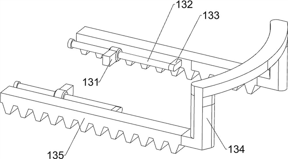
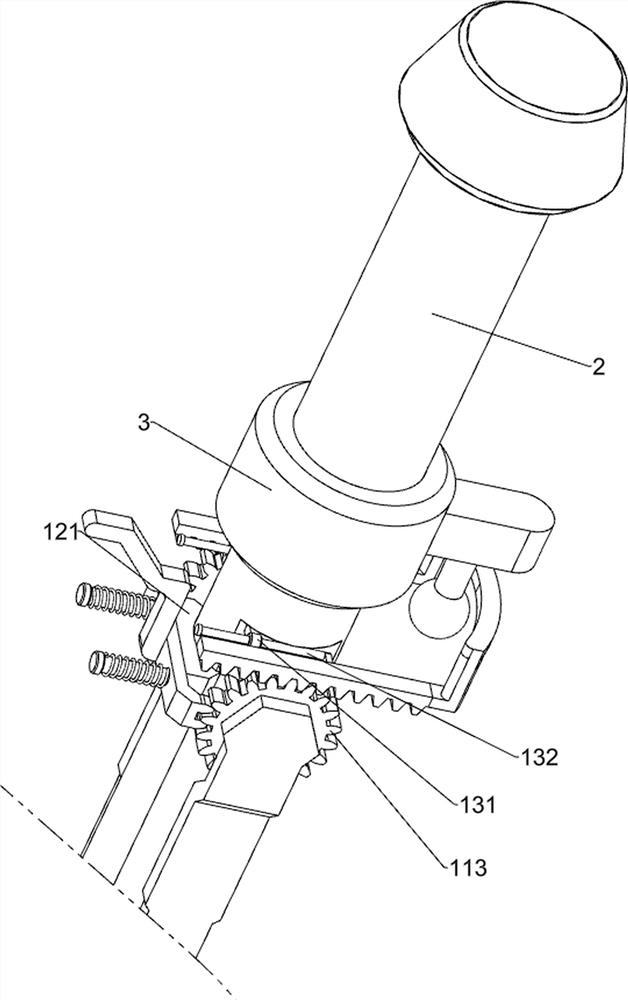
[0039] On the basis of Example 1, as figure 1 , Figure 7 and Figure 8 As shown, it also includes a reset mechanism 13, the reset mechanism 13 drives the scraper 111 to automatically reset to be parallel to the bracket 2, and the reset mechanism 13 includes a guide sleeve 131, a second guide rod 132, a connecting block 133, an arc plate 134 and a rack 135. Guide sleeves 131 are provided on both the front and rear sides of the upper part of the bracket 2. The guide sleeves 131 are slidably provided with second guide rods 132. The right side of the second guide rod 132 is provided with connecting blocks 133, and the connecting blocks 133 are connected to each other. There is an arc-shaped plate 134 , and racks 135 are provided on the front and rear sides of the arc-shaped plate 134 , and the racks 135 are engaged with the adjacent gears 113 .

[0040] When the gear 113 rotates through the rotating rod 112 to drive the scraper 111 to rotate to clean the photovoltaic panel 84, ...

Embodiment 3

[0042] On the basis of Example 2, as figure 1 , Figure 9 , Figure 10 , Figure 11 and Figure 12 As shown, it also includes a limiting mechanism 14. The limiting mechanism 14 includes a limiting block 141, a first sliding sleeve 142, a fourth compression spring 143, a handle 144 and a top block 145. There are three limiting blocks equidistant from the middle of the bracket 2. The position block 141 and the limit block 141 are all provided with a first sliding sleeve 142 , the sliding ends of the first sliding sleeve 142 are all sleeved with a fourth compression spring 143 , and the top of the sliding end of the first sliding sleeve 142 is connected with a top. Block 145, a handle 144 is provided on the top right side of the top block 145.

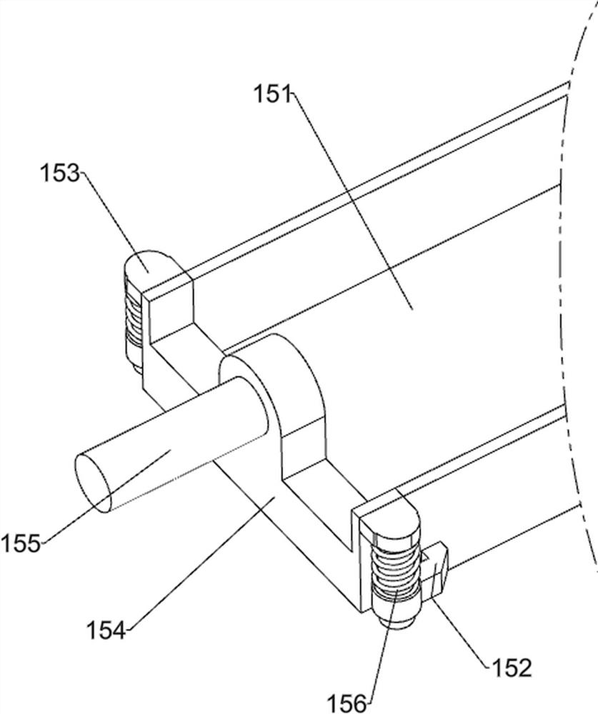
[0043] It also includes a splash-proof mechanism 15, which catches the swept-off dust, and the splash-proof mechanism 15 includes a splash-proof frame 151, a second sliding sleeve 152, a fixed block 153, a baffle 154, a pressure rod 1...


PUM


Abstract

The invention relates to a solar street lamp, in particular to a solar street lamp facilitating improvement of the light energy utilization rate. According to the solar street lamp convenient to improve the light energy utilization rate, manual operation is reduced, electric energy is stored through a photovoltaic panel, and the photovoltaic panel is cleaned. A solar street lamp facilitating improvement of the light energy utilization rate comprises a base, a support, a driving rod, a top rod, a first lamp rod, a mounting frame, a mounting rod and a supporting plate, the support is arranged at the top of the base, the driving rod and the first lamp rod are arranged on the left side of the upper portion of the support, the top rod is arranged on the right side of the driving rod, and the mounting frame is arranged on the left side of the bottom of the driving rod and comprises two mounting hollowed-out plates. Supporting plates are symmetrically arranged on the inner sides of the installation hollowed-out plates left and right, and installation rods are arranged on the inner sides of the supporting plates. By arranging the driving rod which is irradiated by sunlight and then rotates along with the driving rod, the photovoltaic panel is driven to rotate, so that the photovoltaic panel can fully store electric energy, and then the first lamp pole and the second lamp pole are driven to be turned on to illuminate the road surface.

Description

technical field [0001] The invention relates to a solar street lamp, in particular to a solar street lamp which is convenient for improving the utilization rate of light energy. Background technique [0002] With the continuous improvement and maturity of photovoltaic power generation technology, photovoltaic power generation products are becoming more and more abundant, and they are getting closer to people's lives. Solar lighting is one of the more common products that use solar power for lighting. [0003] The patent with the patent authorization announcement number CN201820891131.7 discloses a solar street light with a rotatable solar panel, which includes an electric drive device, a solar controller, a lithium battery, a pillar, a solar panel, N support beams, and electrical equipment. The shape of the pillar is T-shaped or L-shaped, the cross-section of the pillar is a polygonal geometric shape, and the cross-section of the extended section at the top of the T-shaped o...

Claims


Application Information

Patent Timeline
Patent Type & Authority Applications(China)
IPC IPC(8): F21S9/03F21V23/00H02S20/32H02S40/10F21W131/103
CPCF21S9/035F21V23/00H02S20/32H02S40/10F21W2131/103Y02E10/50
Inventor 龙胜福
Owner 龙胜福
Learn More