
Terminal monitoring device for gas pressure reducing valve

A monitoring device and pressure reducing valve technology, applied in valve device, valve operation/release device, valve details, etc., can solve the problems of unlocked fixing hoop, great harm, insufficient socket depth, etc., to reduce accidents , The effect of preventing gas leakage and improving safety

Pending Publication Date: 2022-07-08
宁波市产品食品质量检验研究院(宁波市纤维检验所)
View PDF0 Cites 0 Cited by
  • Summary
  • Abstract
  • Description
  • Claims
  • Application Information

AI Technical Summary

Problems solved by technology

[0003] When installing the existing pressure reducing valve, one end is threaded on the gas tank, and the other end is fixed by the rubber hose socket. The whole process of installation needs manual operation by the user who purchases the product. Problems, such as the hose socket is not firm, the socket depth is not enough or the fixing hoop is not locked, etc., which will lead to the hidden danger of air leakage in the connection part with the rubber hose; and in the gas fires currently sent, many reasons are caused by the user burning Going out while cooking will cause accidents (dishes are not cooked when going out, so keep the gas turned on, and then forget), which is extremely harmful. Set up a terminal monitoring device to solve the above problems

Method used


Image

  • Terminal monitoring device for gas pressure reducing valve
  • Terminal monitoring device for gas pressure reducing valve
  • Terminal monitoring device for gas pressure reducing valve

Examples


Embodiment 1

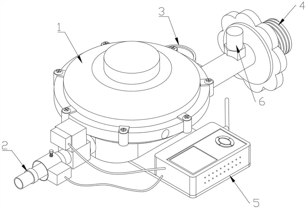
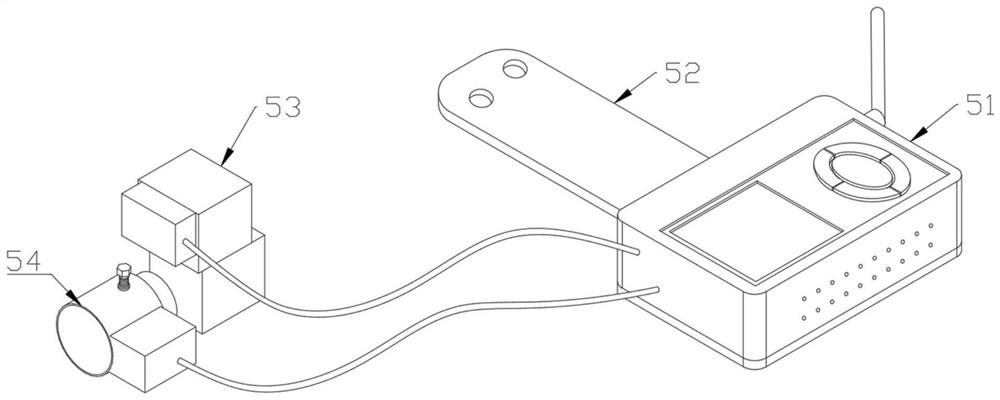
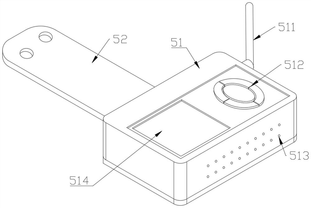
[0025] Example one, by Figure 1-3 and Image 6 Given, the present invention includes a pressure reducing valve body 1, one end of the pressure reducing valve body 1 is connected with one end of an input pipeline, and the other end of the input pipeline is connected with a threaded joint 4, and a pressure gauge 3 and a self-locking module are installed outside the input pipeline. 6. The other opposite end of the main body 1 of the pressure reducing valve is connected with one end of the output pipe, and the other end of the output pipe is connected with a connecting sleeve 2. The connecting sleeve 2 is connected with the external hose, and a clamp is installed to limit the position. The pressure reducing valve A terminal monitoring device 5 is installed at the front end of the main body 1. The terminal monitoring device 5 includes a terminal main body 51, a T-shaped mounting plate 52, an electromagnetic control valve 53 and a locking detection mechanism 54. The bottom of the t...

Embodiment 2

[0027] The second embodiment, on the basis of the first embodiment, is composed of Figure 4-5 Given, the locking detection mechanism 54 includes a connection sleeve 544, one end of the connection sleeve 544 is connected with a detection sleeve 541, and is movably sleeved on the output pipe, and the external thread of the detection sleeve 541 is connected with a plurality of locking screws 543 , and a plurality of locking screws 543 are connected with a rubber block 5431 through the end face of the detection sleeve 541, and a detection module 542 is connected to the outer end of the detection sleeve 541; A plurality of ventilation holes 5411 are opened between 542 and the detection sleeve 541; the gas sensor 5421 is electrically connected to the input of the processing motherboard module; the inner diameter of the detection sleeve 541 is larger than the width of the connection sleeve 2 at the position where the rubber hose is connected and the clamp is installed;

[0028] The ...


PUM


Abstract

The invention discloses a fuel gas pressure reducing valve terminal monitoring device, and relates to the technical field of fuel gas valve detection, the fuel gas pressure reducing valve terminal monitoring device comprises a pressure reducing valve main body, the front end of the pressure reducing valve main body is provided with a terminal monitoring device, and the terminal monitoring device comprises a terminal main body, a T-shaped mounting plate, an electromagnetic control valve and a locking detection mechanism; the bottom of the terminal body is connected with a T-shaped mounting plate, the T-shaped mounting plate is mounted at the bottom of the pressure reducing valve body, and the electromagnetic control valve is electrically connected with the terminal body. According to the invention, when gas leakage occurs at the joint of the connecting sleeve and the rubber sleeve and the gas sensor detects that the gas concentration in the air is higher than a set value, information is sent to the processing mainboard module of the terminal main body, and the processing mainboard module controls the loudspeaker module to sound to remind a user that the installation and connection of the pressure reducing valve go wrong; and data can be sent to a mobile terminal for checking through the wireless communication module, so that gas leakage is prevented, accidents are reduced, and the safety is improved.

Description

technical field [0001] The invention relates to the technical field of gas valve detection, in particular to a terminal monitoring device for a gas pressure reducing valve. Background technique [0002] The pressure reducing valve is an important gas equipment installed on the angle valve of the liquefied gas cylinder to connect the angle valve and the hose to reduce the output pressure and stabilize the output pressure. It has a simple structure, stable pressure, light weight, and adjustable installation. convenience and so on. It is mainly composed of air inlet, air outlet, handwheel, upper valve cover, lower valve cover, air intake nozzle, breathing hole, upper air chamber, decompression chamber, valve pad, lever, rubber film, spring, adjusting screw plug and other components composition. [0003] When the existing pressure reducing valve is installed, one end is threadedly installed on the gas tank, and the other end is fixed with the hose. The whole process of install...

Claims


Application Information

Patent Timeline
Patent Type & Authority Applications(China)
IPC IPC(8): F17C13/04F17C13/02F17D3/01F17D5/00F17D5/02F16K31/06F24C3/12
CPCF17C13/04F17C13/02F17D3/01F17D5/02F17D5/005F16K31/06F24C3/126
Inventor 张幸志蒋仲义陈威刘芳芳
Owner 宁波市产品食品质量检验研究院(宁波市纤维检验所)
Learn More