
Electric door of low-voltage switch cabinet

A low-voltage switchgear and electric door technology, which is applied in the substation/switch layout details, electrical components, door/window accessories, etc., can solve the problems of poor anti-theft performance and achieve the effect of avoiding lock failure and improving anti-theft performance

Pending Publication Date: 2022-07-05
NINGBO TIANAN GRP CO LTD
View PDF1 Cites 2 Cited by
  • Summary
  • Abstract
  • Description
  • Claims
  • Application Information

AI Technical Summary

Problems solved by technology

[0004] The automatic door opening and closing structure controls the rotation of the machine arm through the door opener, and the machine arm transmits power to the slider in the door frame chute, so that the slider makes a reciprocating linear motion in the door frame, driving the door frame to rotate, and realizing the opening or closing of the door frame. , and lock the door frame through the control host to control the electromagnetic lock after the door is closed. However, in order to ensure the effect of automatic opening and closing, the automatic door opening and closing structure uses the electromagnetic lock as the locking tool. The locking function will disappear, and the overall anti-theft performance is poor

Method used


Image

  • Electric door of low-voltage switch cabinet
  • Electric door of low-voltage switch cabinet
  • Electric door of low-voltage switch cabinet

Examples


Embodiment 1

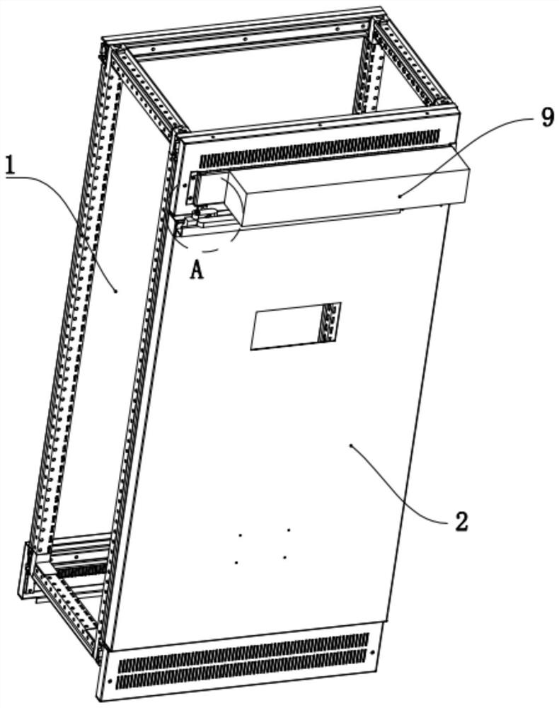
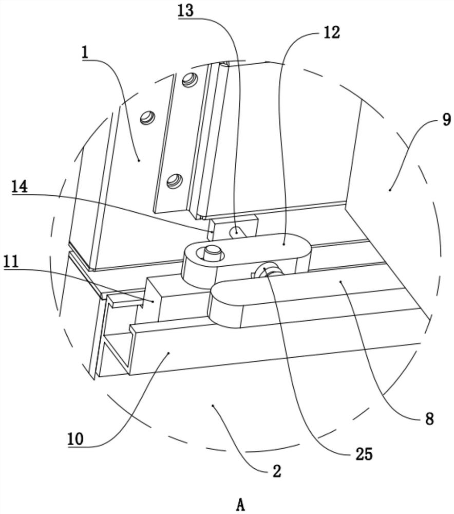
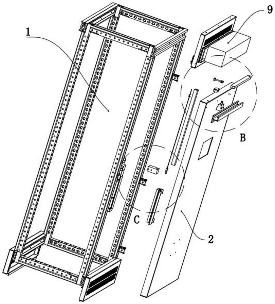
[0052] A low-voltage switch cabinet electric door, refer to Figure 1 to Figure 20 , including the cabinet 1, the cabinet door 2 is hinged on the cabinet 1, can be rotated to open or close the cabinet 1, between the cabinet 1 and the cabinet door 2 is provided with an automatic opening and closing door structure and a locking structure, the locking structure It includes a mounting block 3 arranged on the cabinet body 1, a locking groove 4 is recessed on the top surface of the mounting block 3, a fixing block 5 is provided on the cabinet door 2 above the mounting block 3, and a lower bottom surface of the fixing block 5 is recessed. The telescopic slot 6, a locking block 7 is arranged in the telescopic slot 6, and the locking block 7 is inserted and matched with the locking slot 4 when it descends to realize the locking of the cabinet door 2; when the locking block 7 rises, it is separated from the locking slot 4. , to unlock, the cabinet door 2 can be opened smoothly, the lift...

Embodiment 2

[0059] Compared with Embodiment 1, the difference between this embodiment is that in this embodiment, refer to Figure 21 , the outer wall of the locking block 7 is recessed with a accommodating groove 26, and the accommodating groove 26 is rolled with a roller 27 that fits with the inner wall of the telescopic groove 6. By setting the roller 27, the locking block 7 and the telescopic groove 6 The sliding friction between the two is converted into rolling friction, which reduces the friction between the locking block 7 and the expansion groove 6, and further ensures the smooth lifting of the locking block 7.


PUM


Abstract

The invention relates to the technical field of low-voltage switch cabinets, and discloses a low-voltage switch cabinet electric door which comprises a cabinet body, a cabinet door hinged to the cabinet body and capable of opening or closing the cabinet body, an automatic door opening and closing structure arranged between the cabinet body and the cabinet door and a locking structure arranged between the cabinet body and the cabinet door. The locking structure comprises a mounting block arranged on the cabinet body, a locking groove concavely formed in the upper top surface of the mounting block, a fixed block arranged above the mounting block on the cabinet door, a telescopic groove concavely formed in the lower bottom surface of the fixed block, and a locking block which is arranged in the telescopic groove in a lifting manner and is matched with the locking groove in a penetrating manner during descending or is separated from the locking groove during ascending; according to the electric door of the low-voltage switch cabinet, the anti-theft performance of the low-voltage switch cabinet is improved while the door of the low-voltage switch cabinet is automatically opened and closed.

Description

technical field [0001] The invention relates to the technical field of low-voltage switch cabinets, in particular to an electric door of a low-voltage switch cabinet. Background technique [0002] Low-voltage switchgear can realize the conversion or control of electric energy. Conventional low-voltage switchgear doors are manual. After opening the cabinet door during maintenance, the cabinet door is easy to collide with the cabinet under the action of inertia and cause damage. In severe cases, it will be damaged. As a result, the cabinet door rebounds, and it is easy to squeeze the hands of the workers, so the automatic door opening and closing structure appears. [0003] The Chinese patent with the application number CN201520362889.8 discloses an automatic advertising door for pedestrian passages in a community, comprising a doorpost and a door frame, the door frame is rotatably connected to the door post through a hinge, and a door lock is provided between the other end of...

Claims


Application Information

Patent Timeline
Patent Type & Authority Applications(China)
IPC IPC(8): H02B1/30H02B1/32H02B1/38E05B47/00E05B65/02E05F15/00
CPCH02B1/30H02B1/306H02B1/32H02B1/38E05B65/02E05B47/0002E05F15/00E05Y2999/00
Inventor 徐德勤罗景华叶发勇章程潘荣臻
Owner NINGBO TIANAN GRP CO LTD
Learn More