


Quick Research
Generate reliable direction feasibility study reports for your R&D in just a few steps.

Technical Q&A
Discover and master advanced knowledge NOW. Basics, ideas, possibilities, all at once.

Find Solutions
As an expert in R&D theories, this can generate solutions to your technical problems instantly.

Evaluate Feasibility
Analyze your overall solution with one click, know your potential R&D risks in advance.

Monitor Landscape
Get weekly tech updates, stay abreast of the latest tech innovations and key insights.
High-speed signal TO-CAN structure
A TO-CAN, high-speed signal technology, applied in the field of high-speed signal TO-CAN structure, can solve problems such as power consumption, achieve the effects of reducing signal distortion, increasing impedance matching design, and reducing material costs
- Summary
- Abstract
- Description
- Claims
- Application Information
AI Technical Summary
Problems solved by technology
Method used
Image

Examples
Embodiment 1
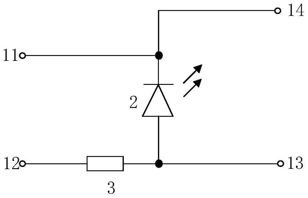
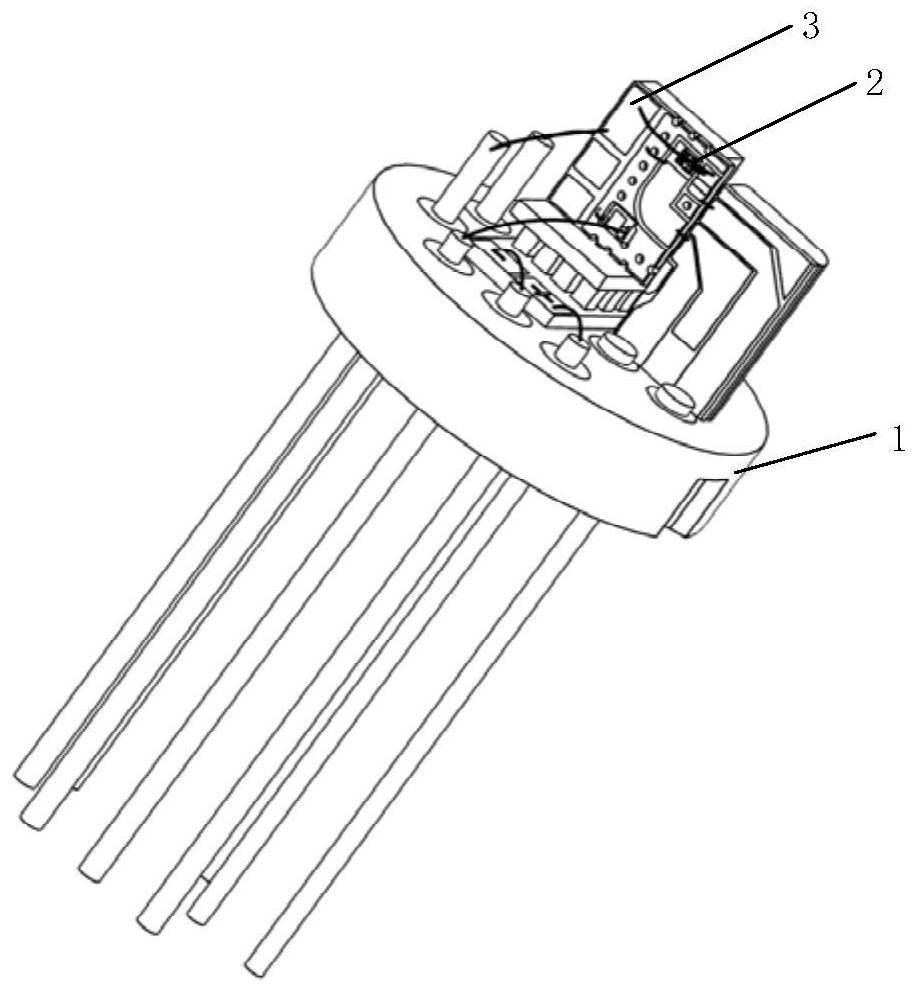
[0041] Embodiment 1 of the present invention provides that the present invention provides a high-speed signal TO-CAN structure, such as figure 1 and figure 2 shown, including TO base 1 and laser chip 2, specifically:
[0042] The TO base 1 is provided with two laser high-frequency signal pins (in figure 2 Marked as 11 and 12), respectively for establishing electrical connection with one end of the matching resistor 3 and one end of the laser chip 2; wherein, the other end of the matching resistor 3 is interconnected with the other end of the laser chip 2;
[0043] The two ends of the laser chip 2 are also respectively connected with the two laser static working pins on the TO base 1 (in figure 2 marked as 13 and 14) in the connection.
[0044] The matching resistor 3 is used to adapt the signal source of the high-frequency signal, the transmission impedance between the high-frequency signal source and the laser, and the balance between the high-frequency impedance of the...
Embodiment 2
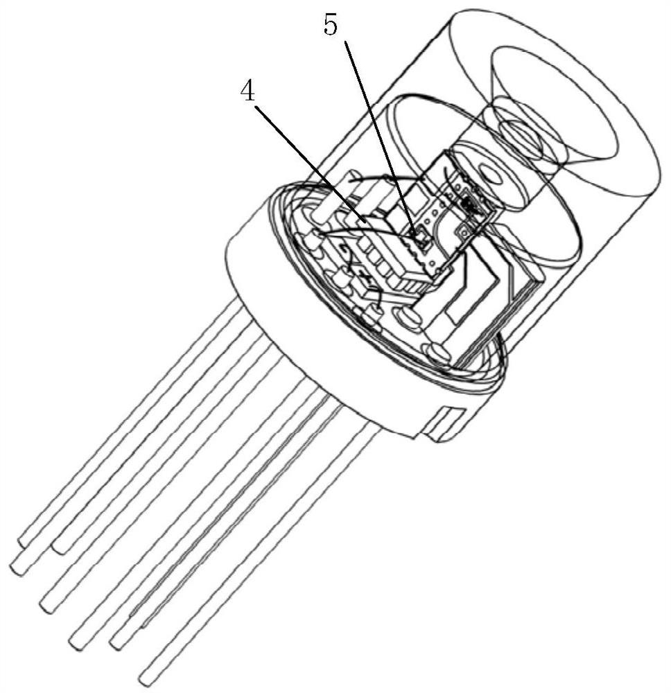
[0060] The technical solution of the embodiment of the present invention is a high-speed signal light-emitting TO with matching resistance to improve power consumption. Compared with Embodiment 1, the embodiment of the present invention presents the content of the solution with a relatively complete structural example.
[0061] The embodiment TO of the present invention consists of a TO base 1, a laser chip 2, a matching resistor 3, a TEC4, a backlight monitoring PD chip 5, a thermistor 6, a ceramic plate 7 carrying the matching resistor 3 and high-speed signal lines, and a tungsten copper block 8 , Aspheric lens cap 9. The laser chip 2 is welded to the ceramic board 7 with matching resistors and high-speed signal lines by eutectic welding, and the backlight monitoring PD chip 5 is bonded to the ceramic board 7 with matching resistors and high-speed signal lines through conductive glue. The ceramic board 7 and the thermistor 6 of the laser chip 2 and the backlight monitoring P...
PUM
 Abstract
Description
Claims
Application Information
 - R&D Engineer
- R&D Manager
- IP Professional
- Industry Leading Data Capabilities
- Powerful AI technology
- Patent DNA Extraction
Browse by: Latest US Patents, China's latest patents, Technical Efficacy Thesaurus, Application Domain, Technology Topic, Popular Technical Reports.
© 2024 PatSnap. All rights reserved.Legal|Privacy policy|Modern Slavery Act Transparency Statement|Sitemap|About US| Contact US: help@patsnap.com