
Adjustable confluence clamp

An adjustable, clamp technology, applied in the direction of clamp connection conductor connection, transportation and packaging, wire wound connectors, etc., can solve the complex structure of the cable crimp body, reduce the current carrying capacity of the system, increase the contact resistance point, etc. problems, to achieve the effect of simple structure, reduced weight, and increased current carrying capacity

Active Publication Date: 2022-07-05
挚行电子(苏州)有限公司
View PDF5 Cites 0 Cited by
  • Summary
  • Abstract
  • Description
  • Claims
  • Application Information

AI Technical Summary

Problems solved by technology

[0003] With the rapid development of urban construction, the requirements for power supply reliability are getting higher and higher, and the frequency of use of various operating vehicles such as box-type vehicles and generator vehicles has increased greatly. The low-voltage side of box-type vehicles and generator vehicles and the busbar Connecting tool confluence clamps are often used when connecting; CN212908472U discloses an adjustable confluence clamp, which includes a clamp body, a cable crimping body and a sleeve rod, and the rear movable clamp head of the clamp body can be far away from or close to The front fixed clamp head can be adapted to clamp cables of different sizes, and the rear movable clamp head can move back and forth through the push-pull rod located in the sleeve rod; in order to facilitate the operation of the push-pull rod, the tail end of the sleeve rod passes through radially The cable crimping body exposes the tail of the push-pull rod. The axis of the sleeve rod and the axis of the cable crimping body are almost vertically intersected. However, this structure makes the structure of the cable crimping body complex, and the cable crimping body rotates around the sleeve rod. Connection, adding additional contact resistance points, will reduce the current carrying capacity of the system and increase the heat generation under the same current, affecting the stability of the system; while increasing the processing and manufacturing costs, the overall weight is relatively large; and after clamping the copper bar , When inserting the cable plug, it needs to bear a large insertion and withdrawal force. If the cable crimping body is installed vertically, a huge torque will be formed between the clamp body and the clamped equipment copper bar to make the bus bar and supporting copper bar in the cabinet The installed insulating parts bear relatively large stress, and a little carelessness during operation can easily cause damage to the insulating parts supporting the installation of the copper bars. Once the insulating parts are damaged, serious electrical accidents will occur

Method used


Image

  • Adjustable confluence clamp
  • Adjustable confluence clamp
  • Adjustable confluence clamp

Examples


Embodiment

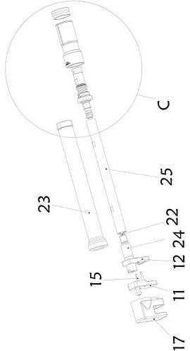
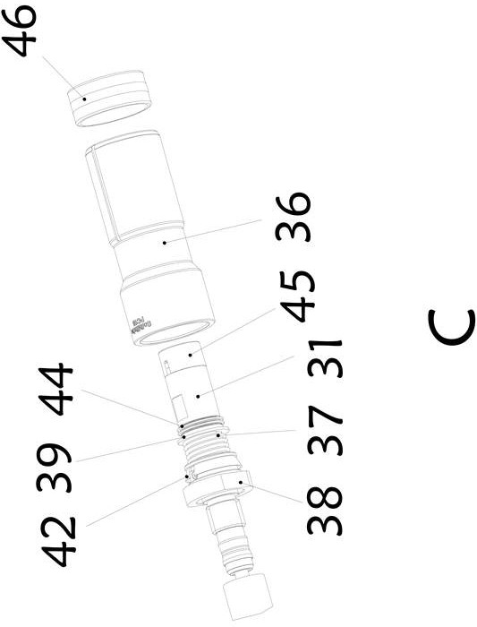
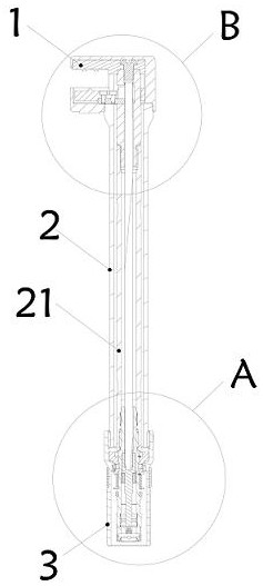
[0022] like Figure 1-5 As shown, an adjustable bus clamp includes a clamp body 1, a clamp arm 2 and a cable connection body 3. The clamp body 1 is detachably connected to the front end of the clamp arm 2, and the cable The connecting body 3 is detachably connected to the rear end of the clamp arm 2 coaxially.

[0023] like Figure 5 As shown, the clamp body 1 includes a front fixed clamp head 11 and a rear movable clamp head 12, the front fixed clamp head 11 and the rear movable clamp head 12 are arranged in an insulating sleeve 17, and the front fixed clamp head 11 A clamping space is formed with the rear movable clamp head 12 . The rear movable clamp head 12 includes a movable clamp plate 13 and a moving block 14 , and the movable clamp plate 13 is fixedly connected with one end of the moving block 14 .

[0024] The movable clamp plate 13 is provided with a guide hole (not shown), and the front fixed clamp head 11 is provided with a guide pin 15. When the movable clamp p...


PUM


Abstract

The invention discloses an adjustable confluence clamp, which comprises a clamp body (1), a clamp arm (2) and a cable connecting body (3), and is characterized in that the clamp body (1) is connected to the front end of the clamp arm (2); the cable connecting body (3) is coaxially connected with the rear end of the clamp arm (2); the clamp body (1) comprises a front fixed clamp head (11) and a rear movable clamp head (12), the clamp arm (2) comprises a conducting rod (21), and a rotating shaft (22) is arranged in a hollow cavity of the conducting rod (21); the cable connecting body (3) comprises a jack sleeve (31) which coaxially sleeves the rear end part of the conducting rod (21); and the rotating shaft (22) rotates to drive the rear movable clamp head (12) to move back and forth. The adjustable confluence clamp is simple in overall structure and light in weight, and safety and operability are improved.

Description

technical field [0001] The invention belongs to the technical field of uninterrupted operation tools for distribution networks, and in particular relates to an adjustable confluence clamp. Background technique [0002] At present, in the process of overhauling the distribution network without power outage, in order to realize the connection between the low-voltage output end of the mobile box-transformer, the emergency generator car and the generator set and the user end, the old-fashioned cable copper nose on the low-voltage cable and the user-end low-voltage cabinet are all used. The internal busbars are connected by bolts. This connection method takes a long time and has the risk of electric shock to the human body. [0003] With the rapid development of urban construction, the requirements for power supply reliability are getting higher and higher, and the frequency of use of various operation vehicles such as box-conversion vehicles and power generation vehicles has gre...

Claims


Application Information

Patent Timeline
IPC IPC(8): H01R11/15H01R11/26H01R43/027H01R4/2475
CPCH01R11/15H01R11/26H01R43/027H01R4/2475Y02T10/7072
Inventor 应伟亮龚海晏
Owner 挚行电子(苏州)有限公司
Learn More