Protection structure and protection method of switch cabinet

A protection structure and switchgear technology, applied in the field of switchgear, can solve the problem of unprotected internal components, and achieve the effects of moisture-proof protection, avoidance of ash and water, and good heat dissipation effect.

Pending Publication Date: 2021-09-07
江苏华彤电气股份有限公司
View PDF2 Cites 0 Cited by
  • Summary
  • Abstract
  • Description
  • Claims
  • Application Information

AI Technical Summary

Problems solved by technology

[0002] The switch cabinet is a kind of electrical equipment. The outside line of the switch cabinet first enters the main control switch in the cabinet, and then enters the sub-control switch. Each branch is set according to its needs, such as instruments, automatic control, motor magnetic switches, various AC contactors, etc. There is also a high-voltage room and a low-voltage room switchgear, with a high-voltage bus, such as a power plant, etc. Although the electrical switchgear is made of steel, it will inevitably be damaged after being exposed to the wind and the sun for a long time. Generally, they are electrically connected to some important outdoor equipment. Once the electrical switchgear is damaged, its internal components will not be protected, which will cause inestimable impact, so reduce the damage of the electrical switchgear and strengthen its use. life is necessary

Method used


Image

  • Protection structure and protection method of switch cabinet
  • Protection structure and protection method of switch cabinet
  • Protection structure and protection method of switch cabinet

Examples


Embodiment 1

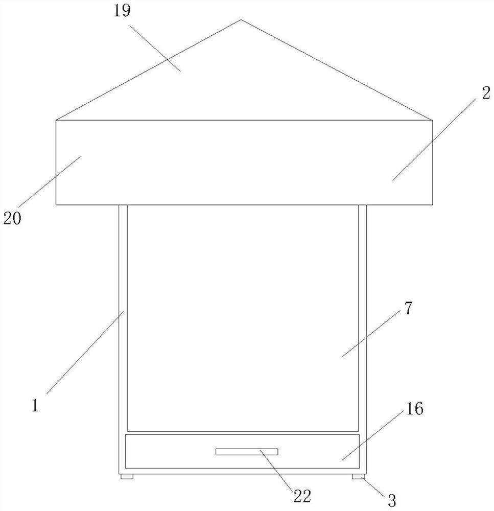
[0031] Such as figure 1 As shown, a protective structure of a switch cabinet includes a switch cabinet body 1 and a protective top cover 2. The bottom of the switch cabinet body 1 is provided with a pad 3, so that there is a gap between the bottom of the switch cabinet body 1 and the ground. distance for air circulation.

[0032] Such as Figure 1-Figure 4 As shown, the top of the protective top cover 2 is inclined, so that rainwater can slide down along the top of the protective top cover 2 without water accumulation.

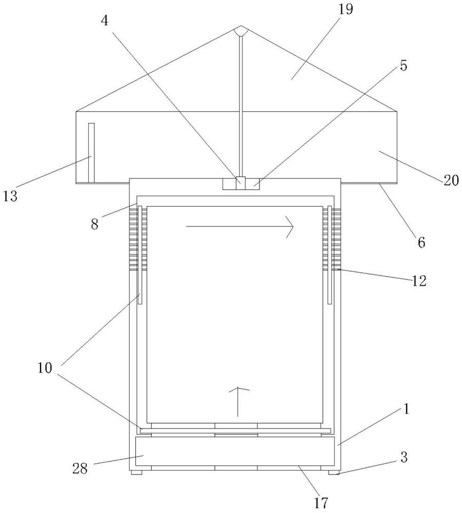
[0033] A cylinder 4 is connected between the top inner wall of the protective top cover 2 and the top wall of the switch cabinet body 1, and the cylinder 4 is used to drive the protective top cover 2 up and down. Installed on the bottom of the installation groove 5.

[0034] The bottom of the protective top cover 2 is provided with a bottom plate 6, and the bottom plate 6 is provided with an opening where the inner wall contacts the side of the switch cabin...

Embodiment 2

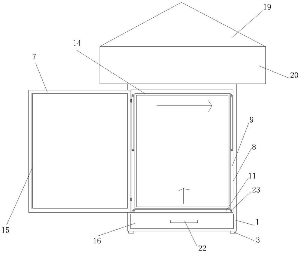
[0045] Such as Figure 1-Figure 5 As shown, compared with Embodiment 1, the protective top cover 2 of the present embodiment includes a top plate 19 and side baffles 20, and the top plate 19 includes two rectangular square top plates 19 and two triangular vertical top plates 19. Two vertical top boards 19 are arranged parallel to each other, the tops of the two square top boards 19 are connected, and the left and right sides of the square top board 19 are connected with the opposite sides of the two vertical top boards 19 respectively. down, to avoid water accumulation at the top of the protective top cover 2.

[0046] The top plate 19 is a triangular prism, and the side baffles 20 are arranged vertically. The top and bottom of the side baffles 20 are respectively connected to the bottom edge of the top plate 19 and the bottom plate 6. The four side baffles 20 are surrounded by the switch cabinet body 1. The bottom plate 6 is arranged horizontally.

[0047] When the cabinet ...

Embodiment 3

[0051] Such as Figure 1-Figure 6 As shown, compared with Embodiment 1, this embodiment is provided with fixed elastic pieces 23 on the steps 9 on both sides opposite to the accommodating cavity 10, one side of the fixed elastic pieces 23 is fixed on the step 9, and the other side of the fixed elastic pieces 23 It is opposite to the accommodating cavity 10 .

[0052] The side of the dustproof plate 11 opposite to the accommodating cavity 10 is provided with a clamping hole 27, and the inner wall of the fixed elastic piece 23 facing the accommodating cavity 10 is provided with a clamping column. When the dustproof plate 11 is completely placed in the accommodating cavity 10, The clamping column can be clamped in the clamping hole 27 .

[0053] When installing the dustproof plate 11, the side of the fixed elastic piece 23 facing the accommodation cavity 10 is pulled up so that it does not block the opening of the accommodation cavity 10, and the dustproof plate 11 is inserted i...


PUM


Abstract

The invention provides a protection structure and a protection method of a switch cabinet. The protection structure comprises a switch cabinet body and a protection top cover. A cushion block is arranged at the bottom of the switch cabinet body, and an air cylinder is connected between the protection top cover and the switch cabinet body. A door frame and a cabinet door are arranged on the switch cabinet body. The door frame is provided with a step. A sealing protruding strip and a sealing groove corresponding to each other are arranged on the cabinet door and the step. Containing cavities are formed in the side face of the bottom of the step and the left side face and the right side face of the step, and dust-proof plates are arranged in the containing cavities. The switch cabinet body, the containing cavities and the interior of the switch cabinet body are communicated through a side ventilation hole channel. When the air cylinder shrinks, the side ventilation hole channel can be completely covered between the bottom plate and the protective top cover, and a first fan in the protective top cover is opposite to the side ventilation hole channel. A drawer is further arranged on the switch cabinet body. The bottom of the switch cabinet body, the drawer, the containing cavities and the interior of the switch cabinet body are communicated through an air inlet duct. A second fan is arranged in the drawer, and a drying agent is arranged between the second fan and the bottom of the drawer.

Description

technical field [0001] The invention relates to the technical field of switch cabinets, in particular to a protection structure and a protection method of a switch cabinet. Background technique [0002] The switch cabinet is a kind of electrical equipment. The outside line of the switch cabinet first enters the main control switch in the cabinet, and then enters the sub-control switch. Each branch is set according to its needs, such as instruments, automatic control, motor magnetic switches, various AC contactors, etc. There is also a high-voltage room and a low-voltage room switchgear, with a high-voltage bus, such as a power plant, etc. Although the electrical switchgear is made of steel, it will inevitably be damaged after being exposed to the wind and the sun for a long time. Generally, they are electrically connected to some important outdoor equipment. Once the electrical switchgear is damaged, its internal components will not be protected, which will cause inestimable...

Claims


Application Information

Patent Timeline
Patent Type & Authority Applications(China)
IPC IPC(8): H02B1/28H02B1/56H02B1/30H02B1/32B01D53/28H02J7/35
CPCH02B1/28H02B1/565H02B1/30H02B1/32B01D53/28H02J7/35
Inventor 赵义平赵晨
Owner 江苏华彤电气股份有限公司
Why Eureka
Try Eureka