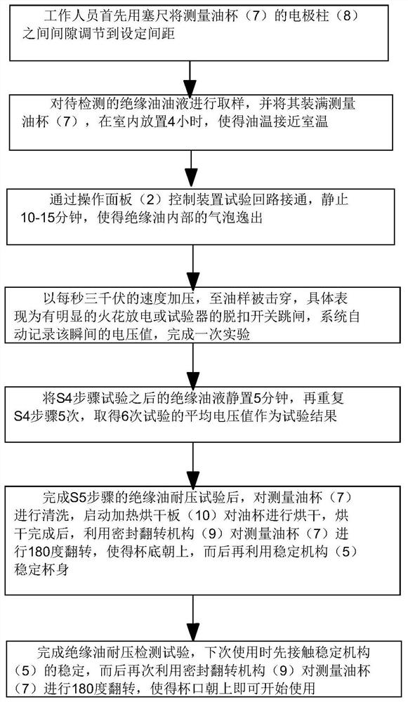
Novel electric power detection device and method
A new type of electric power detection technology, applied in the direction of measuring device casing, testing dielectric strength, etc., can solve the problems of difficult cleaning, difficult test operation, increase the manufacturing cost of the testing device, etc., to reduce manufacturing cost, ensure tightness, and facilitate cleaning. Effect
- Summary
- Abstract
- Description
- Claims
- Application Information
AI Technical Summary
Problems solved by technology
Method used
Image
Examples
Embodiment 1
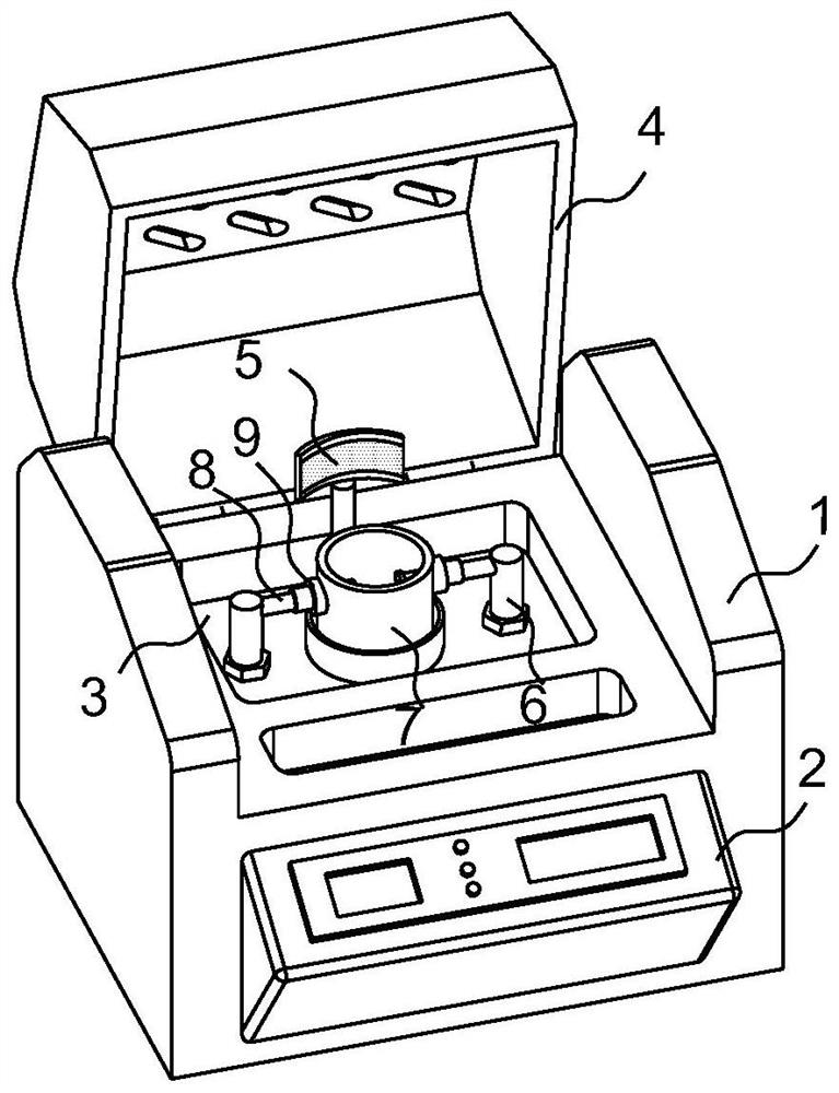
[0046] A new type of power detection device, Figure 2 to Figure 4 As shown, the device comprises a housing 1,
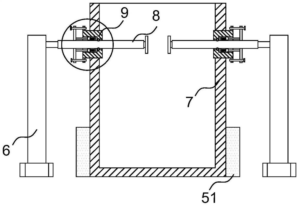
[0047] The outer surface of the casing 1 is fixedly connected to the operation panel 2; the middle position of the upper surface of the casing 1 is provided with an experimental slot 3; The upper end of the test tank 3 is fixedly connected to the electrode column 8; the middle position of the inner bottom of the experimental tank 3 is provided with a measuring oil cup 7, and the two electrode columns 8 penetrate the side wall of the measuring oil cup 7 and extend into the inside of the measuring oil cup 7; the casing 1. The edge position of the upper surface is connected with a shell cover 4 through a hinge rotation;
[0048] The two electrode columns 8 are provided with a sealing overturning mechanism 9 through the position where the side wall of the measuring oil cup 7 is connected to the measuring oil cup 7, which is used to facilitate the overturning of the mea...
Embodiment 2
[0064] like Figure 8 and Figure 9 As shown, the difference between the second embodiment and the first embodiment is:
[0065] The stabilization mechanism 5 includes two outer cylinders 56 symmetrically installed on the outer circular surface of the measuring oil cup 7; the inner parts of the outer cylinders 56 are movably connected to limit rods 57; the middle position of the inner bottom of the experimental tank 3 corresponds to the outer cylinder The position of 56 is provided with two limit holes 58 , and the centerlines of the outer cylinder 56 , the limit rod 57 and the limit holes 58 coincide with each other.
[0066] like Figure 10 As shown, the inner top of the outer cylinder 56 is fixed to the limit spring 59, and the lower end of the limit spring 59 is fixed to the connecting plate 512; A magnet 510; a second magnet 511 is fixedly connected to the upper side of the inner wall of the outer cylinder 56; The cooperation of the first magnet 510 and the second mag...
PUM
 Abstract
Description
Claims
Application Information
 - Generate Ideas
- Intellectual Property
- Life Sciences
- Materials
- Tech Scout
- Unparalleled Data Quality
- Higher Quality Content
- 60% Fewer Hallucinations
Browse by: Latest US Patents, China's latest patents, Technical Efficacy Thesaurus, Application Domain, Technology Topic, Popular Technical Reports.
© 2025 PatSnap. All rights reserved.Legal|Privacy policy|Modern Slavery Act Transparency Statement|Sitemap|About US| Contact US: help@patsnap.com


