
Economical photovoltaic power station with high utilization rate

A photovoltaic power station and utilization rate technology, applied in the direction of photovoltaic power station, photovoltaic module, photovoltaic module support structure, etc., can solve the problems of affecting stability, photovoltaic power station being overturned, photovoltaic power station lack of stable structure, etc., to achieve enhanced stability , the effect of reducing the likelihood

Pending Publication Date: 2022-07-01
江苏富士特电气技术有限公司
View PDF4 Cites 0 Cited by
  • Summary
  • Abstract
  • Description
  • Claims
  • Application Information

AI Technical Summary

Problems solved by technology

In addition, a multi-layer film air bag is added, and the inclination angle of the photovoltaic film panel can be adjusted through selective inflation, which effectively improves its light absorption and photoelectric conversion efficiency." To realize the adjustment of the photoelectric conversion area, and adjust the inclination angle of the photovoltaic thin film panel through the selection of the inflated state, but in the case of strong winds, it is difficult to adjust the center of gravity and accommodate the processing, so that the photovoltaic power station has the possibility of being overturned. Danger;
[0005] 2. Patent document CN108233848B discloses a desert photovoltaic power station equipment, "comprising a fixed base fixed on the land and a rotating seat arranged above the fixed base, a steering motor is embedded in the middle of the fixed base, and the steering The top end surface of the motor is connected with a rotating shaft by power cooperation, and the rotating shaft is fixedly connected with the bottom surface of the rotating seat, a ball bearing is arranged between the fixed base and the rotating seat, and a photovoltaic power generation device is arranged above the rotating seat, In the present invention, the photovoltaic panel can adjust the angle between it and the ground and the overall orientation to adapt to the change of the solar altitude angle, and can also make the photovoltaic panel parallel to the ground in windy and sandy weather to reduce the damage to the photovoltaic panel in windy and sandy weather. In addition, the rain and dew water is collected in the water collection tank and filtered through the sewage filter assembly to irrigate the land under the photovoltaic panels to reduce the degree of desertification." Carry out corresponding management, so that the plant growth is in a disordered state, and then indirectly affect the installation integrity of the equipment;
[0006] 3. The patent document CN108400766B discloses a desert photovoltaic power station, "including an attachment base and a solar photovoltaic panel structure that is plugged and fitted on the attachment base, and the inner wall of the attachment base is provided with a first Sliding groove, the inner wall on the left side of the first sliding groove is provided with a through groove, the left side of the through groove is connected with a left clamping groove, and the left clamping groove runs through the top end surface of the mounting seat body, the The inner wall on the right side of the first sliding groove is provided with a sliding connection groove, the first sliding block is slidably fitted in the first sliding groove, and a threaded rod is installed in the threaded fitting of the first sliding block, and the left side of the threaded rod The extension end is rotationally connected to the first sliding groove, the right extension end of the threaded rod is connected to the first motor through power cooperation, and the outer surface of the first motor is fixed on the right inner wall of the first sliding groove. The first sliding block on the lower side of the threaded rod is fixed with a "sliding plate", and the photovoltaic power station realizes the effective conversion of temperature and heat in the environment during operation, so that the utilization rate of the photovoltaic power station is not high;
The above-mentioned floating photovoltaic power station has the advantages of low maintenance cost, high stability, and does not affect the growth of aquatic animals and plants and the quality of the water body.” The photovoltaic power station lacks a stable structure when it is in use, and it is easy to follow the water flow to move and affect the stability.

Method used


Image

  • Economical photovoltaic power station with high utilization rate
  • Economical photovoltaic power station with high utilization rate
  • Economical photovoltaic power station with high utilization rate

Examples


Embodiment Construction

[0052] The technical solutions in the embodiments of the present invention will be clearly and completely described below with reference to the accompanying drawings in the embodiments of the present invention. Obviously, the described embodiments are only a part of the embodiments of the present invention, rather than all the embodiments. Based on the embodiments of the present invention, all other embodiments obtained by those of ordinary skill in the art without creative efforts shall fall within the protection scope of the present invention.

[0053] In the description of the present invention, it should be noted that the terms "upper", "lower", "inner", "outer", "front end", "rear end", "two ends", "one end" and "the other end" The orientation or positional relationship indicated by etc. is based on the orientation or positional relationship shown in the accompanying drawings, which is only for the convenience of describing the present invention and simplifying the descrip...


PUM


Abstract

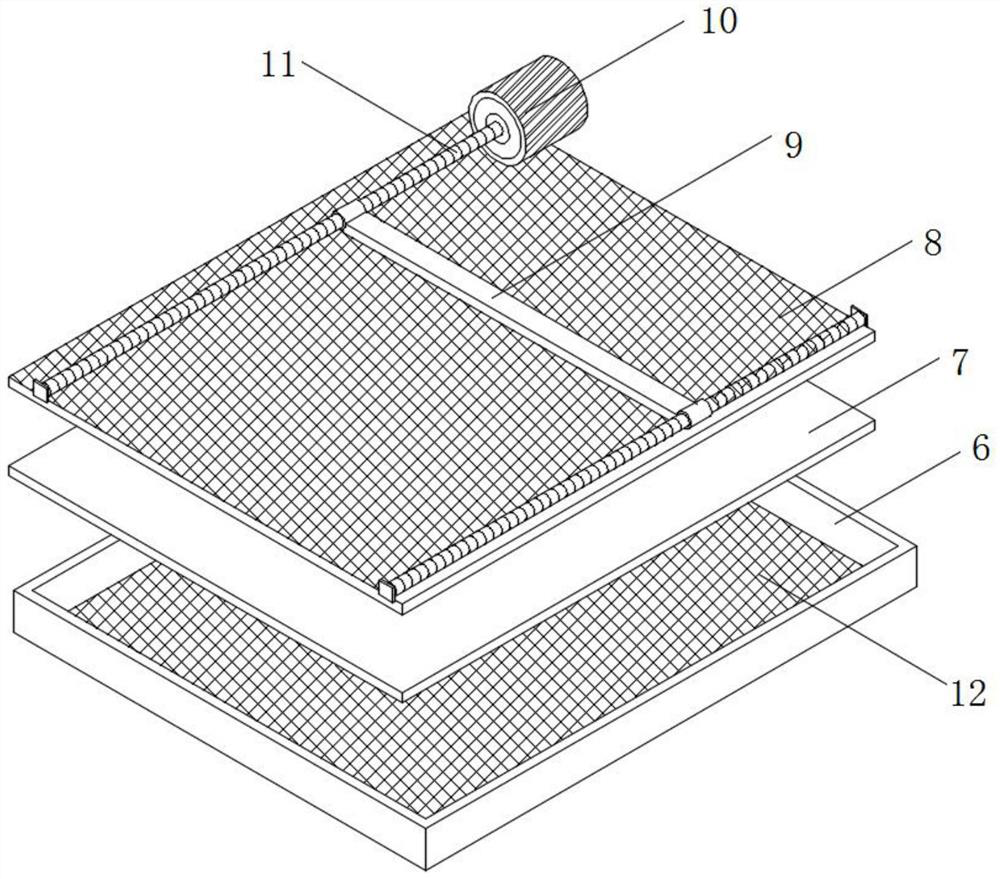
The high-utilization-rate economical photovoltaic power station comprises a lifting rod, a planting frame, an electric telescopic rod and an auxiliary photoelectric box, the top of the lifting rod is slidably connected with a movable rod, and a main photoelectric box is fixed to the top of the movable rod; an electric telescopic rod is installed on the surface of the movable rod through a shaft piece, an auxiliary photoelectric box is connected to the tail end of the electric telescopic rod, the surface of the auxiliary photoelectric box is movably connected with the surface of a main photoelectric box through a hinge, and transparent top covers are installed in the auxiliary photoelectric box and the main photoelectric box correspondingly; and a thermoelectric conversion mechanism is mounted on the inner wall of each transparent top cover. By arranging four groups of auxiliary photoelectric boxes and electric telescopic rods, the angle between the auxiliary photoelectric boxes and the main photoelectric box is adjusted, night high-temperature utilization is realized under the assistance of the thermoelectric conversion mechanism and the winding mechanism, and the energy utilization rate and the economic effect of the photovoltaic power station are further improved.

Description

technical field [0001] The invention relates to the technical field of photovoltaic power stations, in particular to an economical photovoltaic power station with high utilization rate. Background technique [0002] Photovoltaic power station refers to a photovoltaic power generation system that uses solar energy and uses special materials such as crystalline silicon panels, inverters and other electronic components to form an internal power generation system, which is compatible with the power grid and transmits power to the power grid. Distributed small grid-connected photovoltaic systems and centralized large-scale grid-connected photovoltaic power stations, among which distributed small grid-connected photovoltaic systems are mostly installed on the surface of buildings, while centralized large-scale grid-connected photovoltaic power stations are mostly distributed in deserts and outdoors. Considering the utilization rate, it is necessary to improve the energy utilizatio...

Claims


Application Information

Patent Timeline
IPC IPC(8): H02S20/30H02S30/20H02S30/00H02S10/12H02S40/42H02S40/44
CPCH02S20/30H02S30/20H02S30/00H02S10/12H02S40/42H02S40/44Y02E10/50
Inventor 张劲张泽来
Owner 江苏富士特电气技术有限公司
Learn More