
Dual active bridge inductance range determination method suitable for single phase shift control

A technology of dual active bridge and phase-shift control, which is applied in the direction of control/regulation system, electrical components, and adjustment of electrical variables, etc., which can solve the problems of inability to guarantee high reliability of the circuit and incomplete consideration

Pending Publication Date: 2022-07-01
XI AN JIAOTONG UNIV
View PDF0 Cites 1 Cited by
  • Summary
  • Abstract
  • Description
  • Claims
  • Application Information

AI Technical Summary

Problems solved by technology

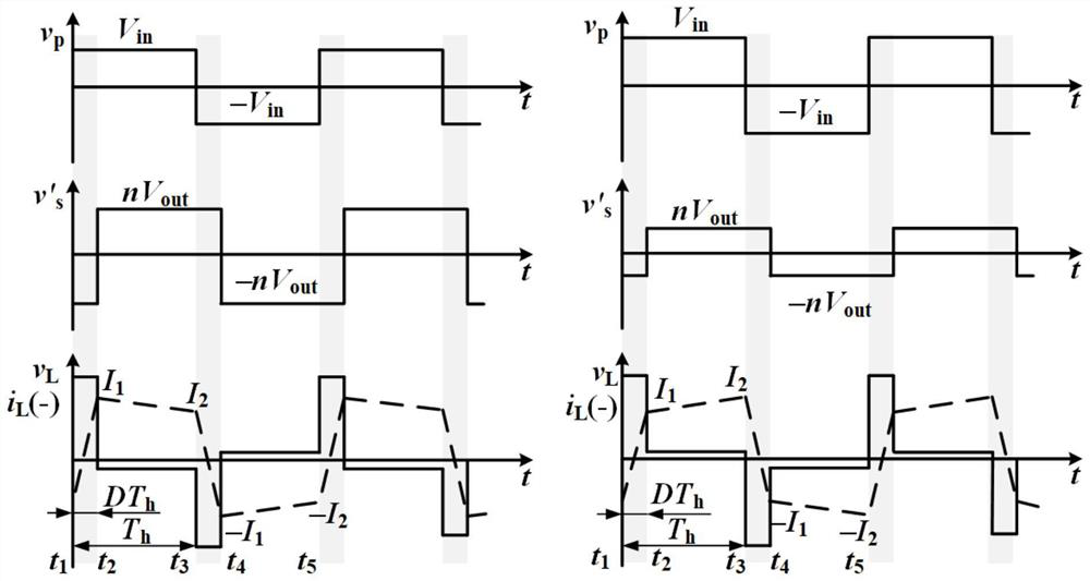
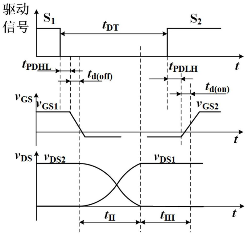
[0007] The purpose of the present invention is to provide a method for determining the inductance range of dual active bridges suitable for single-phase shift control, so as to solve the problems that the above-mentioned existing DAB inductance selection range is not well considered and cannot ensure high reliability of the circuit. The present invention considers the two major constraints of circuit output maximum power requirement and circuit power device zero-voltage switch requirement, and simultaneously considers the characteristic current value direction requirement, inductance energy meeting the primary-side commutation requirement and dead zone when analyzing the zero-voltage switch requirement The matching of time and inductance value requires three major conditions, and the inductance value range that satisfies the three major conditions and two constraints is obtained

Method used


Image

  • Dual active bridge inductance range determination method suitable for single phase shift control
  • Dual active bridge inductance range determination method suitable for single phase shift control
  • Dual active bridge inductance range determination method suitable for single phase shift control

Examples


Embodiment Construction

[0076] The technical solutions in the embodiments of the present invention will be clearly and completely described below with reference to the accompanying drawings in the embodiments of the present invention. Obviously, the described embodiments are part of the embodiments of the present invention, but not all of the embodiments. Based on the embodiments of the present invention, all other embodiments obtained by those of ordinary skill in the art without creative efforts shall fall within the protection scope of the present invention.

[0077] In the description of the present invention, it should be noted that, unless otherwise expressly specified and limited, the terms "comprising" and "comprising" indicate the presence of the described features, integers, steps, operations, elements and / or components, but do not The presence or addition of one or more other features, integers, steps, operations, elements, components and / or sets thereof is not excluded.

[0078] It should...


PUM


Abstract

The invention discloses a dual active bridge inductance range determination method suitable for single phase shift control. The method considers the constraint that the maximum output power of the circuit should be greater than a given output power index requirement, and also considers the constraint that a power device in the circuit should realize a zero-voltage switching requirement. Meanwhile, detailed discussion is conducted on the requirement for the direction of a characteristic current value, the requirement for inductance energy meeting primary side commutation and the requirement for matching of dead zone time and an inductance value, the minimum value of the inductance value range is obtained, the zero-voltage switching performance of a power device in the DAB circuit is guaranteed, and the working reliability of the power device and even the whole device is improved. And meanwhile, the power device does not generate switching loss, so that the loss of the whole circuit is reduced, and the working efficiency of the DAB device is improved. Experiments prove that the inductance range determination method provided by the invention is comprehensive in consideration and clear in process, ensures the reliability of normal work of the dual-active bridge circuit, and has relatively high practical value.

Description

technical field [0001] The invention belongs to the field of manufacture of transformers, rectifiers and inductors, in particular to a method for determining the inductance range of a dual active bridge suitable for single phase shift control. Background technique [0002] Because of its advantages of high efficiency, high reliability, control, and low cost, medium-voltage direct current transmission technology is more and more widely used in power transmission. Generally, the power that a topology can transmit is proportional to the number of power semiconductors it contains, so in several commonly used topologies, Dual Active Bridge (DAB) is very suitable for high-power applications as a DC converter to use. In addition, compared with other resonant converters, DAB is easier to achieve zero voltage switching (Zero Voltage Switching, ZVS), and the bidirectional conversion speed is faster, so DAB is widely used in medium-voltage high-power transmission applications. [000...

Claims


Application Information

Patent Timeline
Patent Type & Authority Applications(China)
IPC IPC(8): H02M3/335H02M1/38H02M1/088
CPCH02M3/33584H02M1/38H02M1/088
Inventor 王来利靳浩源温浚铎董晓博
Owner XI AN JIAOTONG UNIV
Learn More