Adjustable drainage and overflow integrated drainer
An adjustable, integrated technology, applied in water supply installations, buildings, indoor sanitary piping installations, etc., can solve the problems of inability to accommodate different containers, increased manufacturing costs, and cumbersome installation, and achieves reduction of manufacturing and stocking costs. The effect of overflowing water to ensure safety and large circulation area
- Summary
- Abstract
- Description
- Claims
- Application Information
AI Technical Summary
Problems solved by technology
Method used
Image

Examples
Embodiment 1
[0026] Example 1, refer to figure 1 , 2 , 3, 4, 5.
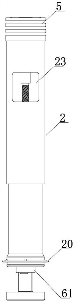
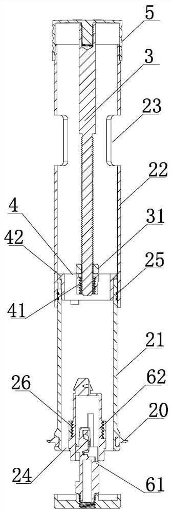
[0027] The improved adjustable drainage and overflow integrated scupper of the present invention includes a fixing component, and the fixing component is provided with a sump 1. The sump is a straight tubular cylinder with a drainage and overflow port 10 on its wall. Both normal drainage and overflow water pass through this port.
[0028] A liftable rigid connection pipe 2 is arranged in the drainage tub, the rigid connection pipe is connected with the switch, and can be operated to descend and ascend. There is a gap 100 between the rigid connection pipe and the drain tank 1. The rigid connection pipe and the drain tank 1 are generally arranged concentrically. The outer diameter of the rigid connection pipe is smaller than the diameter of the drain tank 1. Therefore, the gap 100 has a certain height. annular gap.
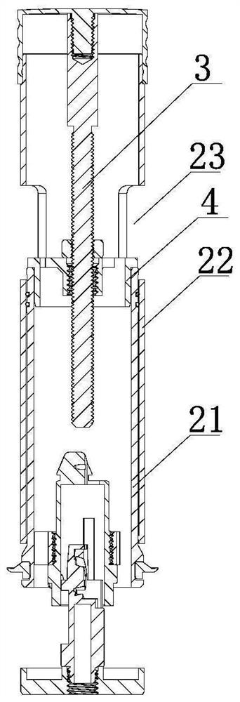
[0029] The lower part of the rigid connection pipe 2 (the lower part of the pipe body 21 of the first part ...
Embodiment 2
[0042] Example 2, refer to Image 6 , 7 , combined with the reference Figure 1-5 .
[0043] In this embodiment, the difference from Embodiment 1 is that the connection structure of the lift drive control input of the liftable rigid connection pipe 2 is changed, so that the drainer of this embodiment can be controlled and driven by the console switch. For other parts of this embodiment, reference may be made to Embodiment 1, and components with the same meaning as those of Embodiment 1 are given the same reference numerals.
[0044] The lower end of the first part is connected to the rod 8 with centering and guiding functions and upward driving force through an internal thread structure 27, and the internal thread structure 27 is connected to the lower end of the first part through a connecting frame.
[0045] The fixing assembly is provided with a lower guide structure that cooperates with the rod member 8 , specifically, a central internal thread structure 80 connected to...
Embodiment 3
[0048] Example 3, refer to Figure 8 , combined with the reference Figure 1-5 .
[0049] In this embodiment, the difference from Embodiment 1 is that the connection structure of the lift drive control input of the liftable rigid connecting pipe 2 is changed, so that the drain of this embodiment can be directly controlled and controlled by the console switch located above. drive. For other parts of this embodiment, reference may be made to Embodiment 1, and components with the same meaning as those of Embodiment 1 are given the same reference numerals.
[0050] The station-controlled switch may be a push switch, a pull-press switch, a rotary switch, and other sanitary control switches that provide two stop positions. This embodiment takes the push switch 9 as an example, the button 5a of the present invention is used as the button of the push switch 9, the force transmission rod 3 runs through the tube body 22 of the second part, and the upper end of the force transmission ...
PUM
 Abstract
Description
Claims
Application Information
 - Generate Ideas
- Intellectual Property
- Life Sciences
- Materials
- Tech Scout
- Unparalleled Data Quality
- Higher Quality Content
- 60% Fewer Hallucinations
Browse by: Latest US Patents, China's latest patents, Technical Efficacy Thesaurus, Application Domain, Technology Topic, Popular Technical Reports.
© 2025 PatSnap. All rights reserved.Legal|Privacy policy|Modern Slavery Act Transparency Statement|Sitemap|About US| Contact US: help@patsnap.com