
Anti-suck-back pressure compensation type irrigation emitter

A pressure compensation and irrigation technology, applied in watering devices, horticulture, agriculture, etc., can solve the problems of capillary irrigation water storage and back suction, irrigation clogging, affecting irrigation efficiency, etc., to ensure safety and consume water flow energy. , the effect of reducing the flow rate of water

Pending Publication Date: 2022-07-01
KUNMING UNIV OF SCI & TECH
View PDF10 Cites 0 Cited by
  • Summary
  • Abstract
  • Description
  • Claims
  • Application Information

AI Technical Summary

Problems solved by technology

However, in actual irrigation production operations, for complex terrain, especially for use in special environments such as mountains and forests, ordinary pressure-compensated emitters cannot guarantee good working results
In addition, because the moment the irrigation is stopped after the normal work of the emitter is completed, the pressure at the water source end will be lost due to the instantaneous loss of pressure, which will cause the phenomenon of sucking back in the capillary, including the water stored inside the emitter. Since the capillary is generally laid on the surface or underground, it is directly connected to the outside It is impossible to avoid the contact with the sand, which will cause the water outlet to suck the sand and cause the blockage of the emitter, which will seriously affect the irrigation efficiency.

Method used


Image

  • Anti-suck-back pressure compensation type irrigation emitter
  • Anti-suck-back pressure compensation type irrigation emitter
  • Anti-suck-back pressure compensation type irrigation emitter

Examples


Embodiment Construction

[0022] In order to make the objectives, technical solutions and beneficial effects of the present invention clearer, the preferred embodiments of the present invention will be described in detail below with reference to the accompanying drawings, so as to facilitate the understanding of the skilled person.

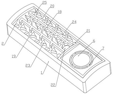
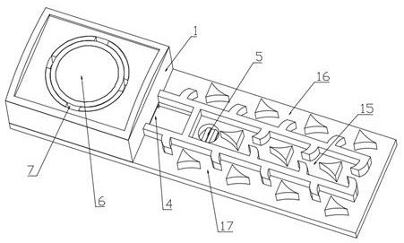
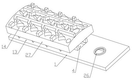
[0023] As shown in the figure, an anti-backdraft pressure compensation type sprinkler includes a main body 1, an energy dissipation cavity 2, and a compensation cavity 3; the main body 1 is provided with an energy dissipation cavity 2 and a compensation cavity 3, and an energy dissipation cavity 2 It communicates with the compensation chamber 3 through the intermediate flow channel 4. An energy dissipation channel is arranged in the energy dissipation chamber 2. One end of the energy dissipation channel is communicated with the intermediate flow channel 4, and the other end is communicated with the water inlet 5 arranged at the bottom of the main body 1. Hedging units for s...


PUM


Abstract

The invention relates to an anti-suck-back pressure compensation type irrigation emitter, and belongs to the technical field of agricultural irrigation. Comprising a body, an energy dissipation cavity and a compensation cavity. An energy dissipation cavity and a compensation cavity are formed in the body, the energy dissipation cavity and the compensation cavity are communicated with each other through a middle flow channel, and an energy dissipation channel is formed in the energy dissipation cavity; a mounting seat is arranged at the top of the compensation cavity, a water outlet is formed in the mounting seat, an elastic membrane and an inner cylinder are sequentially arranged at the bottom of the mounting seat, water retaining rings are uniformly arranged on the inner cylinder at intervals, and annular concave rings matched with the water retaining rings are arranged on the inner wall of the compensation cavity. The water retaining ring and the annular concave ring matched with the water retaining ring are arranged in the compensation cavity, when water at the water source end is cut off, the bottom face of the water retaining ring is tightly attached to the side wall of the bottom of the annular concave ring, sealing is formed, and the problem that external silt is sucked into the irrigation emitter reversely is effectively solved; meanwhile, through the energy dissipation channel, the kinetic energy of water flow can be effectively consumed, the flow speed of the water flow is reduced, the water outlet speeds of all positions are consistent, and the irrigation effect is guaranteed.

Description

technical field [0001] The invention belongs to the technical field of agricultural irrigation, in particular to an anti-suckback pressure compensation type irrigation device. Background technique [0002] The total amount of freshwater resources in my country ranks fourth in the world, but my country's per capita water resources are only 1 / 4 of the world's level, making it one of the poorest countries in the world with per capita water resources, and the distribution of water resources in my country is very different from north to south. my country is also a big agricultural country, and water-saving irrigation is urgent. In actual irrigation production operations, irrigation devices have been widely used nationwide due to their efficient water-saving effect. Different from the common labyrinth channel irrigator, the pressure-compensated irrigator is better than the ordinary labyrinth channel irrigator in actual irrigation production because of better irrigation uniformity a...

Claims


Application Information

Patent Timeline
Patent Type & Authority Applications(China)
IPC IPC(8): A01G25/00
CPCA01G25/00
Inventor 喻黎明朱希茂李娜杨传科余家锐曹丽
Owner KUNMING UNIV OF SCI & TECH
Learn More