Novel rotor topological structure of built-in permanent magnet synchronous motor

A technology of permanent magnet synchronous motor and topological structure, which is applied in the direction of synchronous machine parts, magnetic circuits, electromechanical devices, etc., can solve the problems of reducing the torque output and efficiency output of the motor, limiting the comprehensive performance of the motor, etc., and achieving the improvement of air gap magnetic The effect of dense waveform, reducing torque ripple, and enhancing mechanical strength

Active Publication Date: 2022-06-28
ZHEJIANG UNIV
View PDF4 Cites 0 Cited by
  • Summary
  • Abstract
  • Description
  • Claims
  • Application Information

AI Technical Summary

Problems solved by technology

However, the above method will reduce the torque output and efficiency output of the motor to a certain extent
That is, considering the design of motor torque, efficiency, etc., the torque fluctuation of the built-in permanent magnet synchronous motor and the problems of the mechanical strength of the rotor under high-speed operation will greatly limit the overall performance of the motor

Method used


Image

  • Novel rotor topological structure of built-in permanent magnet synchronous motor
  • Novel rotor topological structure of built-in permanent magnet synchronous motor
  • Novel rotor topological structure of built-in permanent magnet synchronous motor

Examples


Embodiment Construction

[0023] The embodiments of the present invention will be described in detail below with reference to the accompanying drawings. The present embodiment is based on the technical solution of the present invention, and provides detailed implementation modes and specific operation processes, but the protection scope of the present invention is not limited to the following embodiments. .

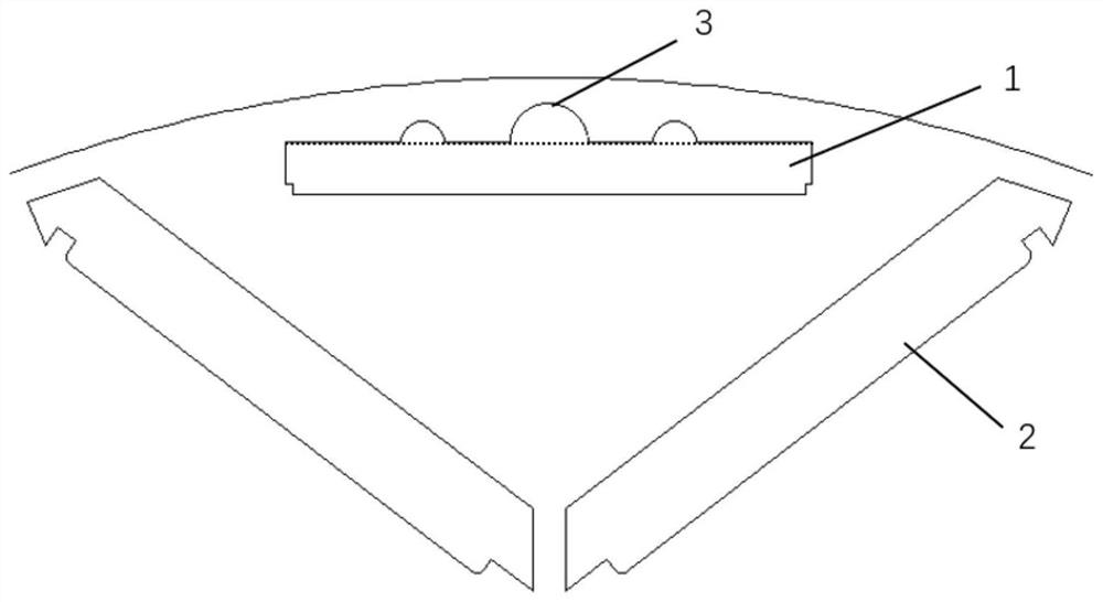
[0024] like figure 1 As shown, at least one magnet is set on the rotor, which is composed of a magnetic isolation magnetic bridge 1 of a "one" type built-in permanent magnet, a magnetic isolation magnetic bridge 2 of a "V" built-in permanent magnet, and a semicircular magnetic barrier 3. Structure; three strip-shaped slots are set on the rotor, and a permanent magnet is fixedly installed in each strip-shaped slot, and a permanent magnet is installed in each of the two strip-shaped slots and arranged in a V-shape to form a "V"-shaped built-in permanent magnet The magnetic isolation magnetic bridge...


PUM


Abstract

The invention discloses a novel rotor topological structure of a built-in permanent magnet synchronous motor. At least one iron core structure is arranged, wherein each iron core structure is composed of a linear built-in permanent magnet magnetism isolating magnetic bridge, a V-shaped built-in permanent magnet magnetism isolating magnetic bridge and a semicircular magnetic barrier. Three strip-shaped grooves are formed in the rotor, two of the strip-shaped grooves are each provided with a permanent magnet, the permanent magnets are arranged in a V shape, and a magnetic isolation magnetic bridge of the V-shaped built-in permanent magnets is formed; a permanent magnet is mounted in each of the remaining strip-shaped grooves, so that a linear magnetic isolation magnetic bridge of the built-in permanent magnets is formed; and a plurality of semicircular hole grooves are formed beside the strip-shaped grooves of the magnetic isolation magnetic bridge of the linear built-in permanent magnet to form a magnetic barrier. According to the invention, the air gap flux density waveform of the motor can be improved, the torque ripple under the motor load is reduced, and the rotor mechanical strength of the motor is enhanced.

Description

technical field [0001] The invention relates to a rotor structure belonging to the technical field of electric motors, in particular to a novel rotor topology of a built-in permanent magnet synchronous motor. Background technique [0002] Permanent magnet synchronous motors have the advantages of high power density and high efficiency, and are suitable for many fields such as electric vehicles and household appliances. Among them, the built-in permanent magnet synchronous motor has additional reluctance torque, which is more widely used in electric vehicles and other fields compared with the surface-mounted permanent magnet synchronous motor, which has larger output torque and stronger field weakening ability. [0003] However, considering the stability and reliability requirements of electric vehicles and other fields, the motor is designed to pursue low torque fluctuation and high mechanical strength of the rotor under high-speed operation. Under normal circumstances, con...

Claims


Application Information

Patent Timeline
Patent Type & Authority Applications(China)
IPC IPC(8): H02K1/2706H02K1/274H02K21/02
CPCH02K1/2706H02K1/274H02K21/02H02K2213/03Y02T10/64
Inventor 黄晓艳周晨曦李赵凯吴敏陈卓马也
Owner ZHEJIANG UNIV
Why Eureka
Try Eureka