


Quick Research
Generate reliable direction feasibility study reports for your R&D in just a few steps.

Technical Q&A
Discover and master advanced knowledge NOW. Basics, ideas, possibilities, all at once.

Find Solutions
As an expert in R&D theories, this can generate solutions to your technical problems instantly.

Evaluate Feasibility
Analyze your overall solution with one click, know your potential R&D risks in advance.

Monitor Landscape
Get weekly tech updates, stay abreast of the latest tech innovations and key insights.
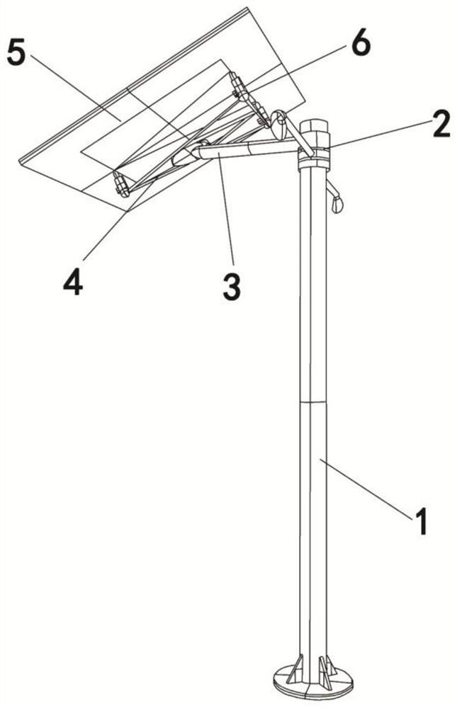
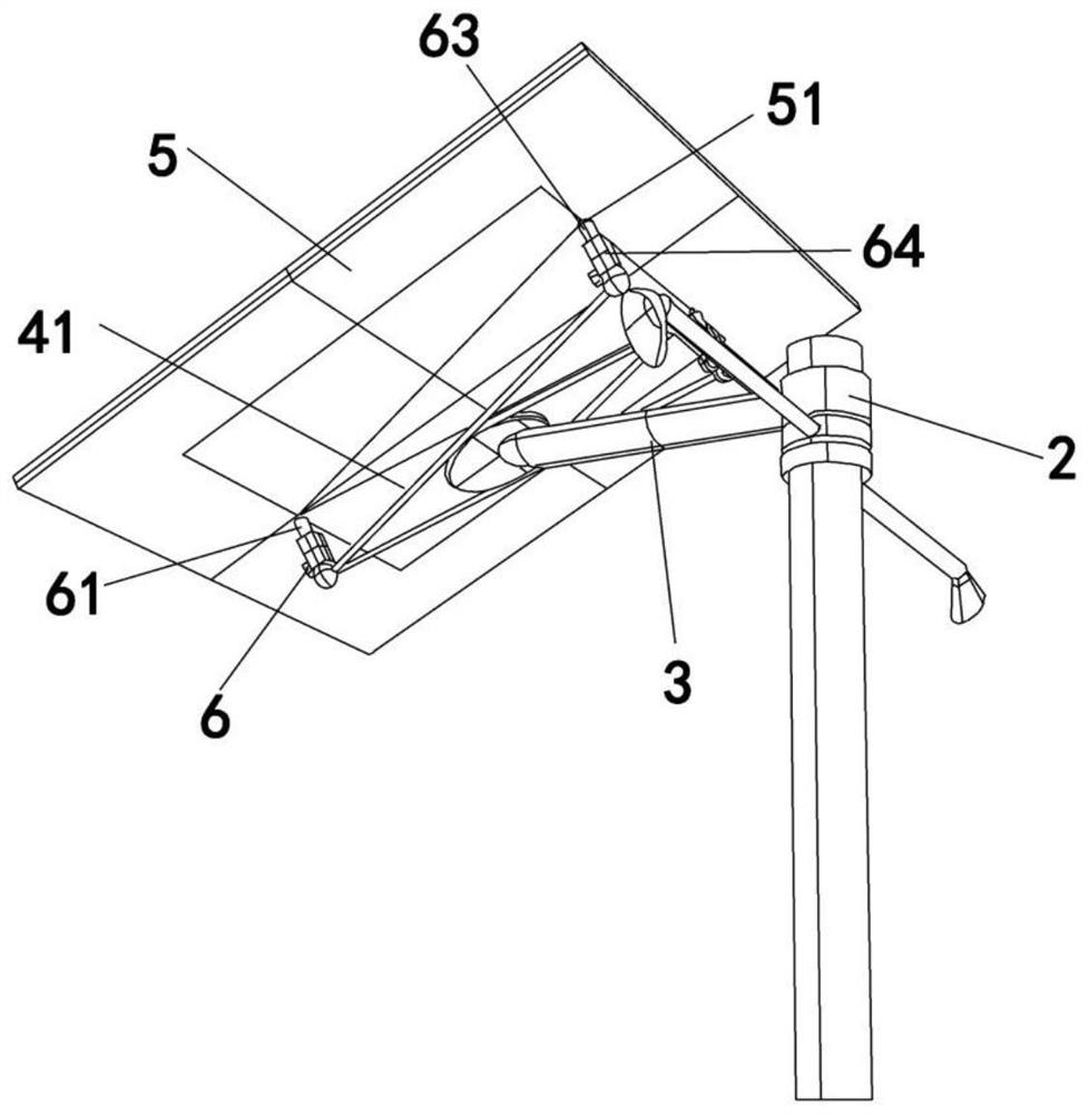
Solar lamp pole
A technology of solar light poles and solar panels, applied in the field of solar street lights, can solve the problems of inability to realize multi-unit linkage, high failure rate, and large difference in absorbed sunlight radiation energy, achieve large photoelectric conversion output, and prolong service life , Precise and easy to adjust the effect
- Summary
- Abstract
- Description
- Claims
- Application Information
AI Technical Summary
Problems solved by technology
Method used
Image

Examples
Embodiment Construction
[0022] In order to make those skilled in the art better understand the technical solutions of the present invention, the present invention will be described in detail below with reference to the accompanying drawings and specific embodiments. The embodiments of the present invention are described in further detail below in conjunction with the accompanying drawings and specific embodiments, but are not intended to limit the present invention.
[0023] "First," "second," and similar words used herein do not denote any order, quantity, or importance, but are merely used to distinguish the different parts. "Comprising" or "comprising" and similar words mean that the element preceding the word covers the elements listed after the word, and does not exclude the possibility that other elements are also covered. "Up", "Down", "Left", "Right", etc. are only used to represent the relative positional relationship, and when the absolute position of the described object changes, the relat...
PUM
 Abstract
Description
Claims
Application Information
 - R&D Engineer
- R&D Manager
- IP Professional
- Industry Leading Data Capabilities
- Powerful AI technology
- Patent DNA Extraction
Browse by: Latest US Patents, China's latest patents, Technical Efficacy Thesaurus, Application Domain, Technology Topic, Popular Technical Reports.
© 2024 PatSnap. All rights reserved.Legal|Privacy policy|Modern Slavery Act Transparency Statement|Sitemap|About US| Contact US: help@patsnap.com