Emergency braking device of wrap yarn machine
A technology for emergency braking and covering yarn machine, applied in yarn, textile and paper making, etc., can solve the problems of high probability of dangerous accidents, low overall safety performance of covering machine, and inability of covering machine to realize emergency braking, etc. To achieve the effect of convenient operation, reduce the probability of safety accidents, and good fixed effect
- Summary
- Abstract
- Description
- Claims
- Application Information
AI Technical Summary
Problems solved by technology
Method used
Image

Examples
Embodiment 1
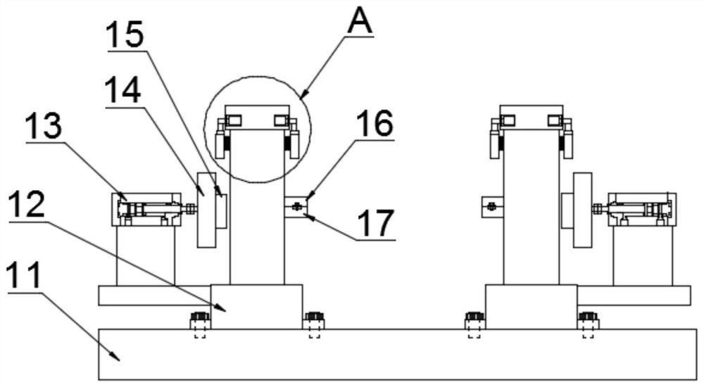
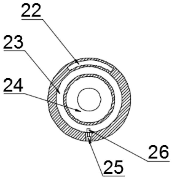
[0045] like Figure 1-5 As shown, this embodiment provides an emergency braking device for a covered yarn machine, including a support base 12 connected to a support base 11 for installing a turntable 24, and the turntable 24 is connected to a yarn covering roller through a Both sides of the roller are connected with a turntable 24; the turntable 24 is provided with an annular groove 23, the support base 12 is connected with a brake plate 14 through a pushing structure, and the brake plate 14 is connected with a brake that is clamped with the annular groove 23 Block 15, the annular groove 23 and the brake block 15 are connected with friction plates; the annular groove 23 and the brake block 15 are connected to the limit block 26 through the first electric telescopic rod 25; the pushing structure and the first electric The telescopic rods 25 are all connected to the PLC controller in communication.
[0046] When the wrapping roller of the wrapping machine needs to be braked ur...
Embodiment 2
[0051] like Figure 1-5 As shown, based on Embodiment 1, the pushing structure of this embodiment includes an air cylinder 13 , the telescopic rod of the air cylinder 13 is connected to the brake plate 14 , and the casing of the air cylinder 13 is connected to the support base 12 .
[0052] During emergency braking, after the staff operates the PLC controller, the cylinder 13 is activated, and the telescopic rod of the cylinder 13 pushes the brake plate 14 to move forward, so that the brake block 15 connected to the brake plate 14 can be inserted into the turntable In the annular groove 23 of 24, after the braking is completed and the accident is handled, the cylinder 13 drives the brake block 15 to move out of the annular groove 23, so that the covering machine can resume normal operation.
[0053] In the present application, the cylinder 13 is used to drive the brake plate 14 to move, which not only makes the operation more convenient for the staff, but also has good driving...
Embodiment 3
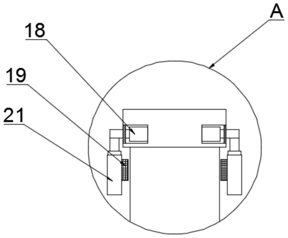
[0055] like Figure 1-5 As shown, based on Embodiment 1, the detachable connector of this embodiment includes a fixing slot 17 connected to the turntable 24, the fixing slot 17 is hinged with a fixing cover 16, and the fixing cover 16 and the fixing slot 17 are locked by a bolt assembly. tight.
[0056] When installing the wrapping roller, snap both sides of the wrapping roller into the fixing groove 17, then turn the fixing cover 16, and then lock the fixing cover 16 and the fixing groove 17 with the bolt assembly. When the wrapping roller is removed, the bolt assembly is removed, and the wrapping roller can be taken out from the fixing groove 17 to realize disassembly.
[0057] The detachable connector used in this application makes it more convenient for the staff to install and disassemble the wrapping roller, and at the same time, it also improves the fixing effect of the wrapping roller, reduces the probability of stopping the wrapping process, and then starts the to i...
PUM
 Abstract
Description
Claims
Application Information
 - R&D
- Intellectual Property
- Life Sciences
- Materials
- Tech Scout
- Unparalleled Data Quality
- Higher Quality Content
- 60% Fewer Hallucinations
Browse by: Latest US Patents, China's latest patents, Technical Efficacy Thesaurus, Application Domain, Technology Topic, Popular Technical Reports.
© 2025 PatSnap. All rights reserved.Legal|Privacy policy|Modern Slavery Act Transparency Statement|Sitemap|About US| Contact US: help@patsnap.com