
Metal storage cage for metal roller transportation

A technology of storage cages and metal rollers, which is applied in the field of storage, can solve problems such as loose connections, damaged goods, easy shaking and collision of side panels, and achieve the effects of avoiding abnormal shaking and collisions, improving applicability, and reducing total weight increase

Inactive Publication Date: 2022-06-28
钛辉制辊(苏州)有限公司
View PDF0 Cites 0 Cited by
  • Summary
  • Abstract
  • Description
  • Claims
  • Application Information

AI Technical Summary

Problems solved by technology

[0003] The existing metal storage cages are equipped with rotatable and open side panels for the convenience of cargo loading and unloading. These side panels are only fixed by simple latches and spring clips, which are not stable enough and are easily loosened due to vibration during transportation. Falling off, and the connection is not tight, causing the side plate itself to easily shake and collide with the goods or the metal storage cage, resulting in damage to the goods and abnormal wear of the metal storage cage. Although there are some restrictions by bolts or similar means, the insertion of bolts The position or locking position is only a hole or slot structure. After a long period of wear and tear, the hole slot will become larger, and the link will still shake after the link, resulting in a weak link; and when using a forklift to transfer the metal storage cage, the metal storage cage The bottom structure is not strong enough, and the metal storage cage is easy to deform. Therefore, it is necessary to design a metal storage cage for metal roller transportation to address the above problems. have technology

Method used

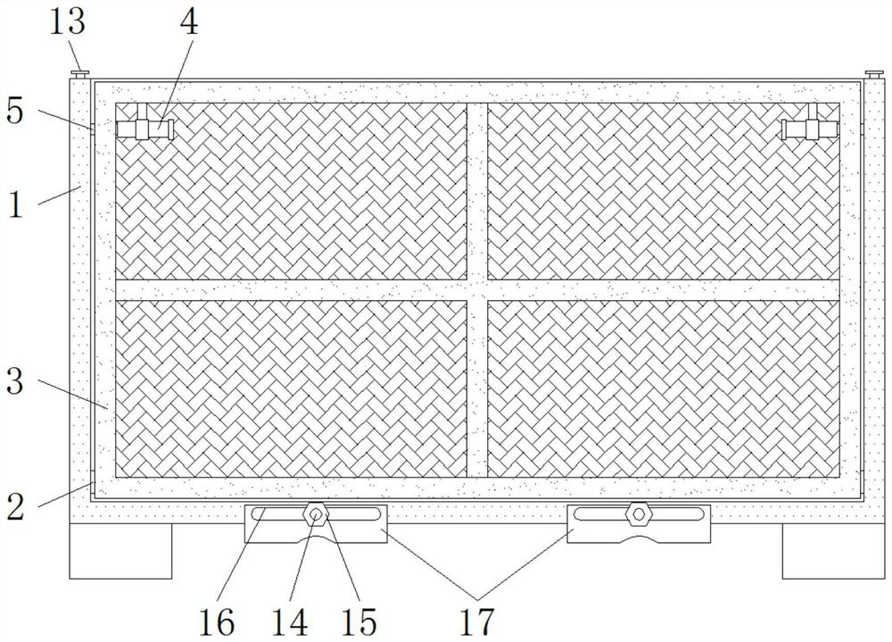
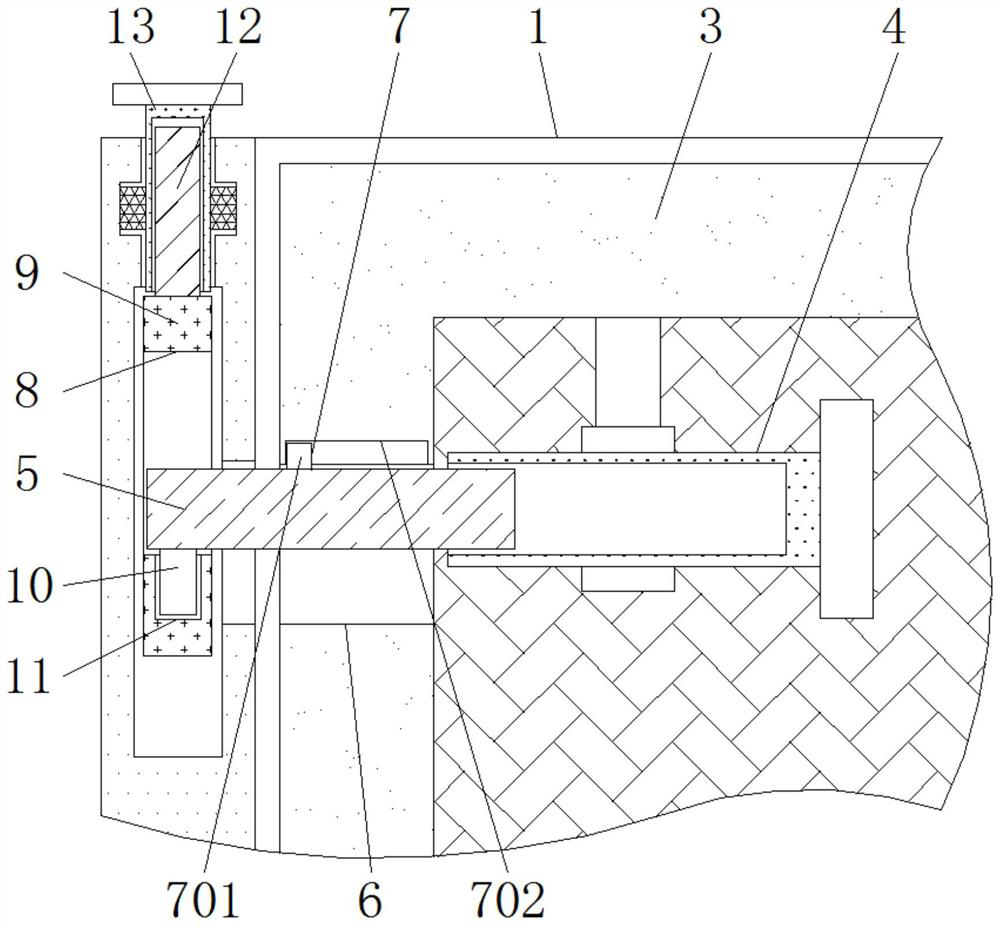
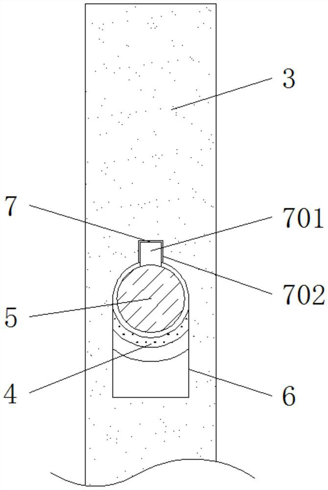

Image

  • Metal storage cage for metal roller transportation
  • Metal storage cage for metal roller transportation
  • Metal storage cage for metal roller transportation

Examples


Embodiment Construction

[0021] In order to more clearly illustrate the overall concept of the present invention, the following detailed description is given by way of example in conjunction with the accompanying drawings.

[0022] In the description of the present invention, it should be understood that the terms "center", "upper", "lower", "front", "rear", "left", "right", "vertical", "horizontal", The orientation or positional relationship indicated by "top", "bottom", "inner", "outer", "axial", "radial", "circumferential", etc. is based on the orientation or positional relationship shown in the drawings, only It is to facilitate the description of the present invention and to simplify the description, rather than indicating or implying that the device or element referred to must have a particular orientation, be constructed and operate in a particular orientation, and therefore should not be construed as limiting the invention.

[0023] In addition, the terms "first" and "second" are only used for...


PUM


Abstract

The metal storage cage comprises a storage cage body, a bottom shaft is installed on the inner wall of the storage cage body, a locking column is welded and fixed to the bottom of the tail end of a horizontal threaded rod, the locking column is attached to the inner wall of a locking hole, and the locking hole is formed in the bottom of a contact window. The top of the positioning plate is fixedly welded to the bottom end of a top threaded rod, the top end of the top threaded rod is in threaded connection with a vertical sleeve, a bottom bolt is fixedly welded to the side of the bottom of the storage cage body, a fastening nut is installed at the tail end of the bottom bolt, the bottom bolt penetrates through a track window, and the track window is formed in a reinforcing plate. According to the metal storage cage for storage, the novel structural design is adopted, the side plates can be stably positioned, stability of the side plates is guaranteed, abnormal shaking and collision of the side plates are avoided, meanwhile, an adjustable reinforcing structure is arranged at the bottom of the metal storage cage, it is guaranteed that the bottom of the metal storage cage does not deform when transferred through a forklift, and the service life of the metal storage cage is prolonged. And the total weight of the metal storage cage is slightly increased.

Description

technical field [0001] The invention belongs to the technical field of storage, and in particular relates to a metal storage cage used for metal roller transportation. Background technique [0002] Metal storage cage is an important storage and transportation container. It is generally made of welded angle steel and steel wire mesh. It has the advantages of fixed storage capacity, neat stacking, clear storage, and easy inventory checking. It also improves the efficiency of storage space. Utilization, some storage cages can also be freely folded, and can be folded and stored when not in use, saving warehouse space. [0003] The existing metal storage cages are provided with side panels that can be rotated and opened to facilitate the loading and unloading of goods. These side panels are only fixed by simple latches and spring sheets, which have insufficient stability and are easily loosened due to vibration during transportation. Falling off, and the connection is not tight,...

Claims


Application Information

Patent Timeline
Patent Type & Authority Applications(China)
IPC IPC(8): B65G1/02B65D88/52B65D88/58B65D90/00B65D90/08B65D90/12
CPCB65G1/02B65D88/528B65D88/58B65D90/00B65D90/08B65D90/12
Inventor 王少明
Owner 钛辉制辊(苏州)有限公司
Learn More