Eureka AIR delivers breakthrough ideas for toughest innovation challenges, trusted by R&D personnel around the world.

Multi-instrument visual tracking method for laparoscope-holding robot in field of view of laparoscope

A visual tracking and laparoscopy technology, applied in surgical robots, instruments, computer components, etc., to achieve the effect of improving clinical applicability, low time cost, and improving positioning accuracy

Pending Publication Date: 2022-06-24
济南国科医工科技发展有限公司
View PDF0 Cites 0 Cited by
  • Summary
  • Abstract
  • Description
  • Claims
  • Application Information

AI Technical Summary

Problems solved by technology

Obviously, the single-instrument visual tracking method is limited to the application scenario where there is only one surgical instrument in the field of view of the laparoscope. However, surgical tasks such as organ tissue cutting and suturing in laparoscopic surgery usually require the surgeon to control two surgical instruments to complete, which is more complicated. The surgery requires a surgical assistant to control two surgical instruments

Method used


Image

  • Multi-instrument visual tracking method for laparoscope-holding robot in field of view of laparoscope
  • Multi-instrument visual tracking method for laparoscope-holding robot in field of view of laparoscope
  • Multi-instrument visual tracking method for laparoscope-holding robot in field of view of laparoscope

Examples


Embodiment Construction

[0046] The technical solutions in the embodiments of the present invention will be clearly and completely described below with reference to the accompanying drawings in the embodiments of the present invention. Obviously, the described embodiments are only a part of the embodiments of the present invention, but not all of the embodiments. Based on the embodiments of the present invention, all other embodiments obtained by those of ordinary skill in the art without creative efforts shall fall within the protection scope of the present invention.

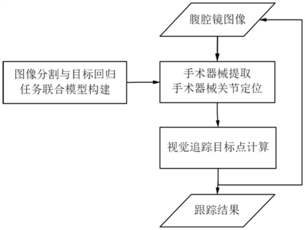
[0047] See figure 1 , figure 1 Shown is the main work flow of the present invention. The present invention proposes a multi-instrument visual tracking method in a laparoscopic field of view for a mirror-holding robot, which includes the following steps: image segmentation and target regression task joint model construction, obtaining the current laparoscopic vision Image frames, extract the surgical instrument area synchronously, loc...


PUM


Abstract

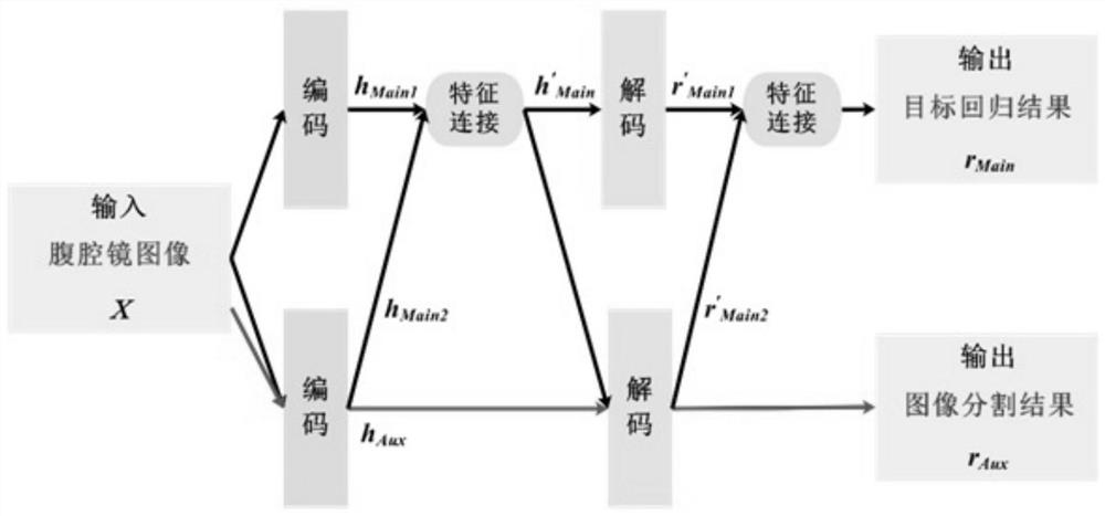
The invention provides a multi-task learning strategy-based multi-instrument visual tracking method in a laparoscope visual field, and the method comprises the steps: constructing a light-weight image segmentation network and a target regression network based on a light-weight LinkNet-18 neural network architecture, synchronously and rapidly extracting regions of all parts (a rod shaft and an end executor) of surgical instruments in a laparoscope image, and carrying out the recognition of all parts (a rod shaft and an end executor) of the surgical instruments in the laparoscope image; accurately positioning the joint position of the surgical instrument in the laparoscopic image in real time; on the basis of a multi-task learning strategy, an image segmentation network and a target regression network are coupled in an iterative interaction mode, a lightweight image segmentation and target regression task joint model is constructed, regions of all parts (a rod shaft and an end effector) of a surgical instrument in a laparoscopic image are synchronously and rapidly extracted, and meanwhile the joint position of the surgical instrument is accurately positioned. And calculating a visual tracking target point in the laparoscope image, and finally realizing real-time accurate tracking of multiple instruments in the field of view of the laparoscope.

Description

technical field [0001] The technical problem to be solved by the present invention is to rapidly and synchronously track multiple surgical instruments in the laparoscopic field of view based on the laparoscopic surgical video. The technology belongs to the field of laparoscopic surgery navigation and robotics. Background technique [0002] In laparoscopic surgery, the hand holding the mirror needs to hold and adjust the position of the laparoscope in time according to the requirements of the chief surgeon, so as to provide the surgeon with a stable and appropriate operative field image in time. However, holding the laparoscope for a long time may cause the hand holding the mirror. Fatigue, hand tremors, and distraction often lead to abnormally jittery images in the surgical field. In addition, it is difficult to cooperate between the mirror holder and the chief surgeon, and communication is inefficient, which ultimately greatly reduces the efficiency of the operation. Aimin...

Claims


Application Information

Patent Timeline
Patent Type & Authority Applications(China)
IPC IPC(8): G06T7/246G06T7/73G06V10/26G06V10/62G06V10/80G06V10/774G06V10/82G06V20/60G06N3/04G06K9/62A61B17/00A61B34/30A61B34/32A61B34/20
CPCG06T7/246G06T7/73A61B17/00234A61B34/30A61B34/32A61B34/20G06T2207/20081G06T2207/20084G06T2207/30004A61B2034/302G06N3/045G06F18/253G06F18/214
Inventor 张家意高欣
Owner 济南国科医工科技发展有限公司
Why Eureka
Eureka Blog
Learn More