
Distributed optical fiber temperature measurement system and method

A distributed optical fiber and optical fiber technology, which is used in thermometers, heat measurement, measurement devices, etc., can solve the problems of difficult fitting of node temperature, inability to integrate data, and lack of feedback temperature correction, so as to facilitate temperature measurement processing and realize real-time correction. , the effect of improving temperature measurement efficiency

Pending Publication Date: 2022-06-24
湖北泓烨智能监测技术服务有限公司
View PDF0 Cites 2 Cited by
  • Summary
  • Abstract
  • Description
  • Claims
  • Application Information

AI Technical Summary

Problems solved by technology

[0005] The main purpose of the present invention is to provide a distributed optical fiber temperature measurement system and method, which can effectively solve the problems in the background technology that the temperature of the nodes in the optical signal transmission process is difficult to fit, the overall data integration cannot be carried out, and the problem of lack of necessary feedback temperature correction

Method used


Image

  • Distributed optical fiber temperature measurement system and method

Examples


Embodiment Construction

[0025] In order to make the technical means, creative features, achievement goals and effects realized by the present invention easy to understand, the present invention will be further described below with reference to the specific embodiments.

[0026] In the description of the present invention, it should be noted that the terms "upper", "lower", "inner", "outer", "front end", "rear end", "two ends", "one end" and "the other end" The orientation or positional relationship indicated by etc. is based on the orientation or positional relationship shown in the accompanying drawings, and is only for the convenience of describing the present invention and simplifying the description, rather than indicating or implying that the indicated device or element must have a specific orientation, with a specific orientation. The orientation configuration and operation are therefore not to be construed as limitations of the present invention. Furthermore, the terms "first" and "second" are...


PUM


Abstract

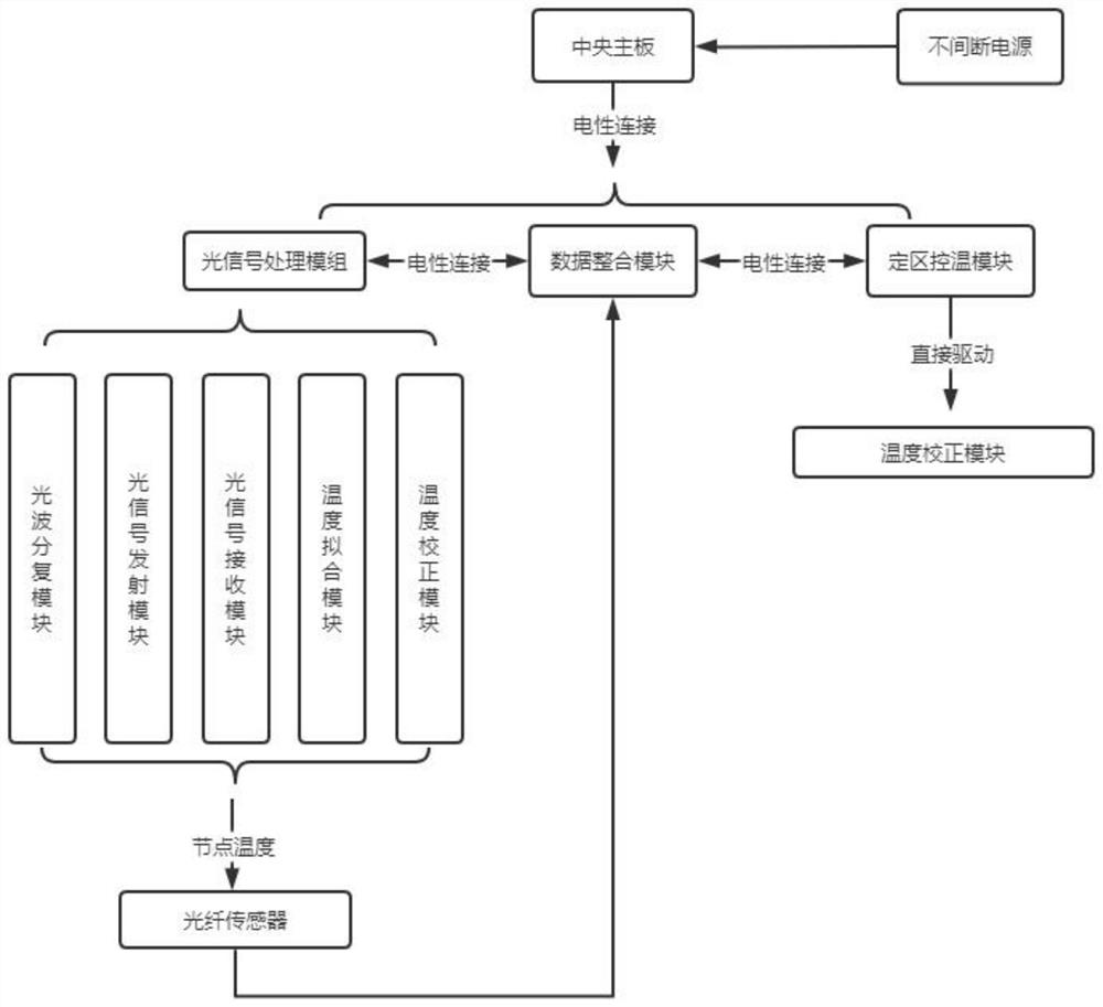
The invention discloses a distributed optical fiber temperature measurement system and method, and relates to the technical field of optical fiber temperature measurement, and the system comprises a central mainboard, and an optical signal processing module, a data integration module and a fixed-area temperature control module which are electrically connected to the central mainboard, and the optical signal processing module, the data integration module and the fixed-area temperature control module are electrically connected. The optical signal processing module comprises an optical signal transmitting module and an optical signal receiving module, the optical signal transmitting module transmits optical pulse data into optical fibers to detect the temperature of an arrangement area, the temperature data is measured by the optical fiber sensors, and the optical signal receiving module receives the temperature data measured by the optical fiber sensors and sends the temperature data to the optical fiber sensors; according to the invention, the temperature fitting module is used for fitting a plurality of nodes of the temperature of the non-arrangement area, so that the temperature of the non-arrangement area is calculated.

Description

technical field [0001] The invention relates to the technical field of optical fiber temperature measurement, in particular to a distributed optical fiber temperature measurement system and method. Background technique [0002] Optical fiber is short for optical fiber. It is a fiber made of glass or plastic, which can be used as a light transmission tool. The tiny optical fiber is encapsulated in a plastic sheath, so that it can be bent without breaking. The transmitting device uses a light-emitting diode or a laser to transmit the light pulse to the optical fiber, and the receiving device at the other end of the optical fiber detects the pulse using a photosensitive element. The temperature is different, and the necessary temperature measurement correction processing is required. [0003] The main temperature measurement method is to use the distributed optical fiber temperature sensing technology, which mainly uses the correlation between the intensity of the Raman scatte...

Claims


Application Information

Patent Timeline
Patent Type & Authority Applications(China)
IPC IPC(8): G01K11/32
CPCG01K11/32
Inventor 张智曹孟辉宋雷田梦园章东贵
Owner 湖北泓烨智能监测技术服务有限公司
Learn More