Squeezing type peristaltic pump
A peristaltic pump, squeeze-type technology, applied in the field of peristaltic pumps, can solve problems such as pipeline deviation and large catheter wear, and achieve the effects of reducing pulsation, increasing life, and improving flow stability
- Summary
- Abstract
- Description
- Claims
- Application Information
AI Technical Summary
Problems solved by technology
Method used
Image

Examples
Embodiment 1
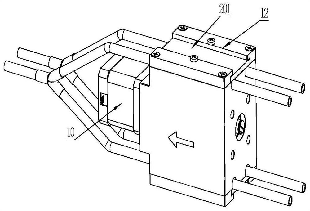
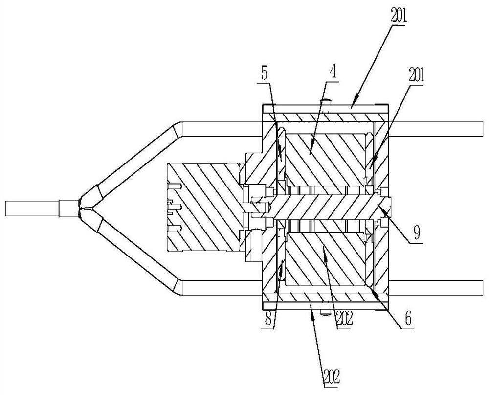
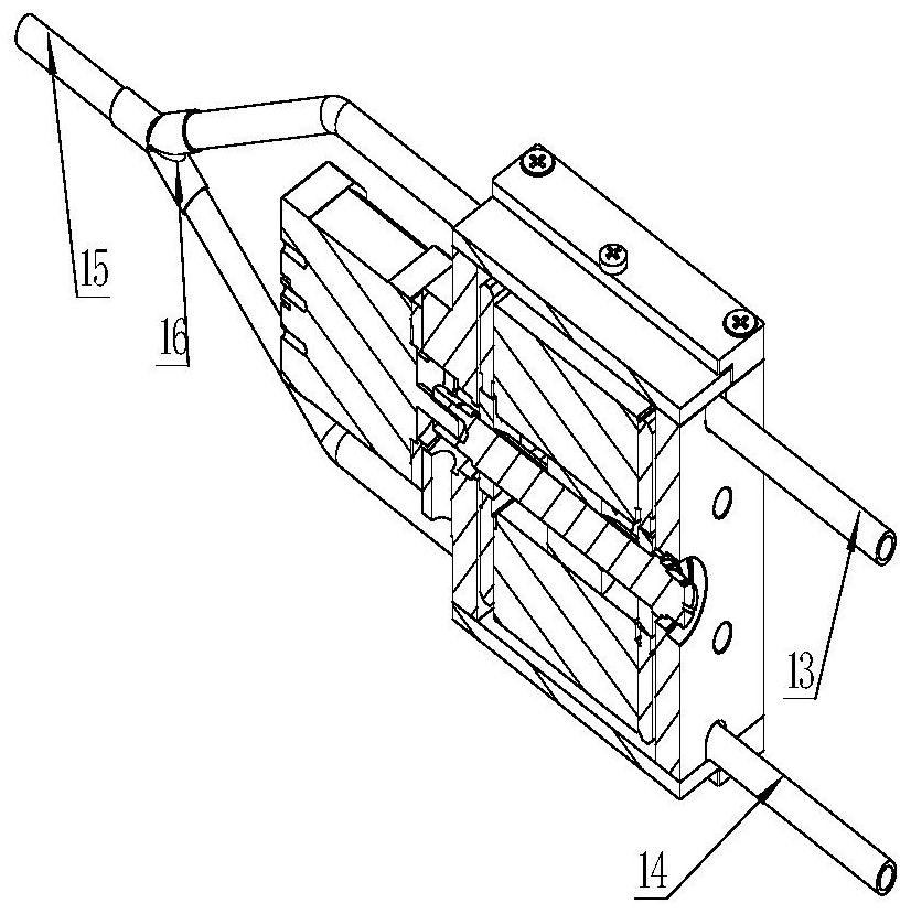
[0077] like Figure 1-7 As shown, the squeeze type peristaltic pump includes: a main body 1, a transmission component (camshaft 9), a first pressing unit (including: a first liquid inlet cut-off block 3, a first working pressure block 4, a first liquid discharge cut-off block Block 5), the second pressing unit (including: the second liquid inlet cut-off block 6, the second working pressure block 7, the second liquid discharge cut-off block 8), the hose (including the first branch pipe 13, the second branch pipe 14, the summary tube 15), the first limiting plate 201, the second limiting plate 202. The first limiting plate 201 and the second limiting plate 202 are respectively disposed on the upper and lower sides of the main body 1 and are fixedly connected with the main body 1 by screws.
[0078] The hose includes a first branch pipe 13 , a second branch pipe 14 , a collective pipe 15 and a tee joint 16 for connecting the above three components.
[0079] The first branch pip...
Embodiment 2
[0115] Different from the first embodiment, the transmission component includes a first transmission unit and a second transmission unit, the first pressing unit reciprocates under the driving of the first transmission unit, and the second pressing unit is in the Reciprocating motion is performed under the driving of the second transmission unit. That is, the first pressing unit and the second pressing unit are individually controlled.
[0116] It should be noted that the first transmission unit and the second transmission unit are not related, and the structures of the two may be the same or different. Similarly, the structures of the first pressing unit and the second pressing unit may be the same or different.
[0117] In this embodiment, one limit plate may be used to limit the two branches of the hose at the same time. Two can also be used to limit the two branches of the hose respectively.
[0118] With this design, the structure is more complicated, the occupied volu...
Embodiment 3
[0121] Different from the first embodiment, the transmission component can be a link mechanism, and one end of the pressing unit performs linear reciprocating motion (such as Figure 8 shown), squeeze the hose periodically.
[0122] like Figure 8 As shown, the first link 17 can be rotated with one end as the center, and then the first link 17 drives the second link 18 to rotate, and the second link 18 pushes the slider 19 to move along a straight line, wherein the slider 19 can be used as an extrusion part Squeeze the hose.
[0123] Among them, the liquid inlet cut-off cam, the extrusion cam and the work cut-off cam can all adopt the above structures.
PUM
 Abstract
Description
Claims
Application Information
 - R&D
- Intellectual Property
- Life Sciences
- Materials
- Tech Scout
- Unparalleled Data Quality
- Higher Quality Content
- 60% Fewer Hallucinations
Browse by: Latest US Patents, China's latest patents, Technical Efficacy Thesaurus, Application Domain, Technology Topic, Popular Technical Reports.
© 2025 PatSnap. All rights reserved.Legal|Privacy policy|Modern Slavery Act Transparency Statement|Sitemap|About US| Contact US: help@patsnap.com