
Geotechnical engineering static sounding equipment and engineering application

A technology of static penetration and geotechnical engineering, applied in the field of geotechnical engineering, can solve the problems of single probe function, affecting detection effect, low detection accuracy, etc., and achieve the effect of increasing the contact area

Pending Publication Date: 2022-06-24
湖州振豪岩土工程有限公司
View PDF0 Cites 0 Cited by
  • Summary
  • Abstract
  • Description
  • Claims
  • Application Information

AI Technical Summary

Problems solved by technology

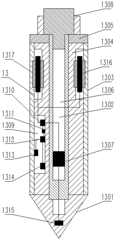
[0006] Solve the problem that the existing static penetration testing equipment cannot be applied to in-situ soft soil, general cohesive soil, silt, sandy soil or soil layers containing a small amount of gravel, nor can it be applied to backfill soil, silt soil and tidal flats , and requires the cooperation of large-scale auxiliary equipment. In addition, the function of the probe of the current general static penetrating equipment is relatively single, the probe is easy to be skewed, and the detection element installed at the tip cannot meet the detection requirements for hard soil layers. The detection accuracy is low during detection, the detection data cannot be stored in time, and the detection effect is affected. Moreover, the data transmitted by the existing static probe head is transmitted by wire, and the wire is too long to affect the working process. It provides a geotechnical Engineering static penetrating equipment and engineering application

Method used


Image

  • Geotechnical engineering static sounding equipment and engineering application
  • Geotechnical engineering static sounding equipment and engineering application
  • Geotechnical engineering static sounding equipment and engineering application

Examples


Embodiment Construction

[0035]A kind of geotechnical engineering static penetration equipment and engineering application of the present invention will be further described in conjunction with the accompanying drawings, and the present invention will be further described in detail below in conjunction with the embodiments:

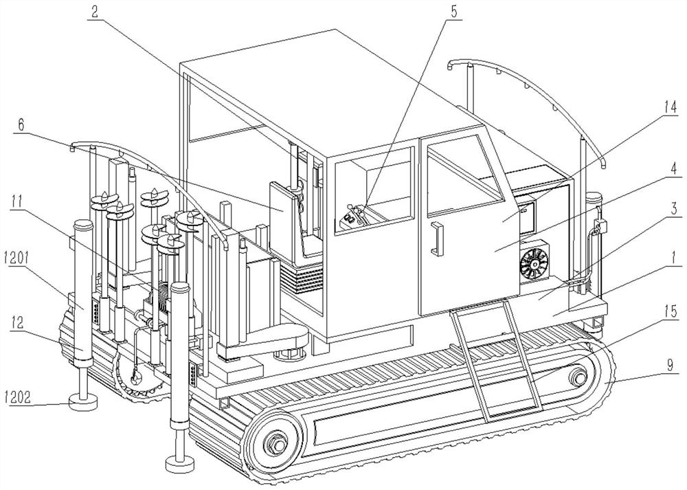
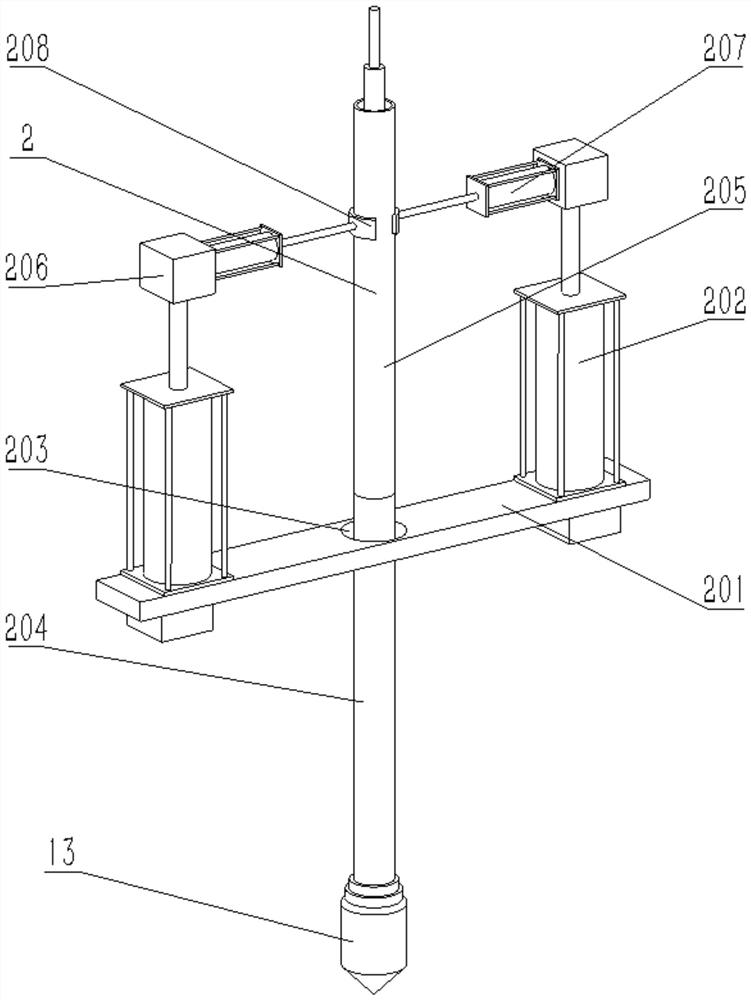
[0036] like figure 1 Shown: a geotechnical engineering static penetration equipment, including a traveling device 1, a static penetration device 2, the traveling device 1 includes a base 3, a housing 4 is fixed on the base 3, and a housing 4 is installed inside the housing 4. Driving platform 5, a driving seat 6 is installed next to the driving platform 5, the static penetration device 2 is arranged beside the driving seat 6, a bottom plate 7 is fixed on the lower surface of the base 3, and a crawler frame 8 is fixed on the lower surface of the bottom plate 7. The crawler frame Covered crawler belts 9 are installed on both sides of 8, a drive mechanism 10 for driving the covered ...


PUM


Abstract

The invention belongs to the technical field of geotechnical engineering, and particularly relates to geotechnical engineering static sounding equipment and engineering application, the geotechnical engineering static sounding equipment comprises a walking device, the walking device comprises a base, a machine shell is fixed on the base, a navigation bridge is installed in the machine shell, a driver seat is installed beside the navigation bridge, and a static sounding device is arranged beside the driver seat. A bottom plate is fixed to the lower surface of the base, a crawler frame is fixed to the lower surface of the bottom plate, crawler belts are installed on the two sides of the crawler frame, a driving mechanism used for driving the crawler belts to walk is arranged on the crawler frame, a winch is installed on one side of the base, a door is installed on the side, close to a driver seat, of the machine shell, and stairs are installed on the side, close to the door, of the base. Stabilizing devices used for stabilizing the equipment are arranged at the four corners of the base, the static sounding equipment not only can be applied to in-situ soft soil, common cohesive soil, floury soil, sandy soil or a soil layer containing a small amount of gravel, but also can be applied to backfill soil, silt soil and mud flat, and large auxiliary equipment is not needed to be matched with the static sounding equipment.

Description

technical field [0001] The present invention is in the technical field of geotechnical engineering, in particular to a geotechnical engineering static penetration equipment and engineering application. Background technique [0002] In the field of geotechnical engineering exploration, static penetration is an exploration method and an in-situ testing method. Static penetration is to press the metal probe into the soil continuously at a certain speed with static force to measure the resistance of the probe. Based on the correlation between the specific penetration resistance and some physical and mechanical properties of the soil, some indicators of the soil are quantitatively determined. According to the pressurization method, static penetration can be divided into three types: manual type, mechanical type and hydraulic type. [0003] Static penetration testing can not only accurately divide the soil layer, but also can quickly, economically and continuously measure certai...

Claims


Application Information

Patent Timeline
Patent Type & Authority Applications(China)
IPC IPC(8): E02D1/00
CPCE02D1/00
Inventor 宋振宋德候鲁长海宋均国
Owner 湖州振豪岩土工程有限公司
Learn More