Vehicle control method, device, equipment and medium
A vehicle control and vehicle technology, which is applied in control devices, vehicle components, transportation and packaging, etc., and can solve the problems of low accuracy and hysteresis of vehicle speed determination.
- Summary
- Abstract
- Description
- Claims
- Application Information
AI Technical Summary
Problems solved by technology
Method used
Image

Examples
Embodiment 1
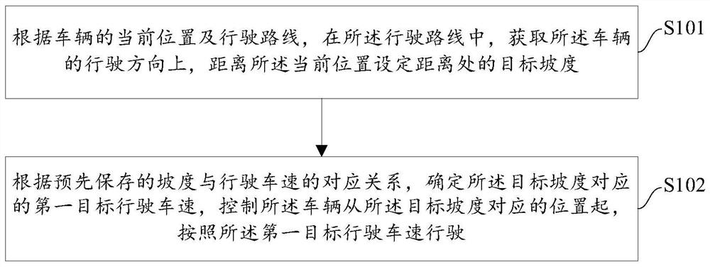
[0055] figure 1 The schematic diagram of the vehicle control process provided in the embodiment of the present application, the process specifically includes the following steps:
[0056] S101: According to the current position of the vehicle and the travel route, in the travel route, obtain a target gradient at a distance from the current position in the travel direction of the vehicle.
[0057] The vehicle control process provided by the embodiments of the present application is applicable to smart cars.
[0058] During the driving process of the vehicle, in order to be able to determine in time what speed the vehicle should drive at when there is a slope on the road section, in this embodiment of the present application, according to the current driving position of the vehicle and the driving route, in the driving route, Get the target slope at the set distance from the current position in the direction of travel of the vehicle. The driving route may be determined based o...
Embodiment 2
[0065] In order to improve the safety of driving, on the basis of the above-mentioned embodiment, in the embodiment of the present application, after acquiring the target gradient at the set distance from the current position in the driving direction of the vehicle, the determining Before the first target vehicle speed corresponding to the target gradient, the method further includes:
[0066] When the target gradient is greater than the first preset gradient threshold, prompt information indicating that the road ahead is too steep is output.
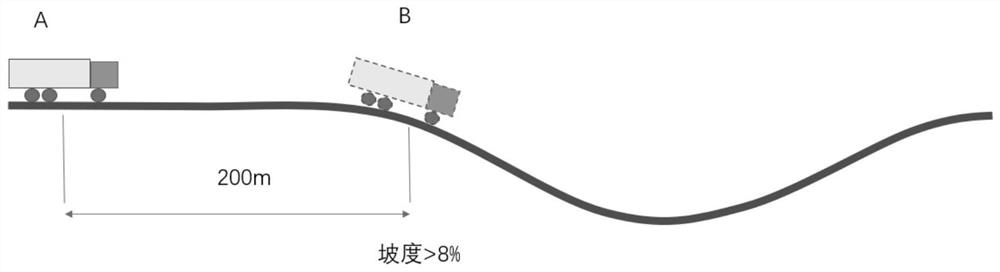
[0067] In order to improve driving safety, after the target gradient is determined, it can be determined whether the target gradient is greater than a first preset gradient threshold, where the first preset gradient threshold can be a specific gradient value, for example, the first preset gradient The gradient threshold may be 15° or a proportional value, for example, the first preset gradient threshold may be 8% of 90°.
[0068] When ...
Embodiment 3
[0072] In order to improve the accuracy of vehicle speed determination, on the basis of the above embodiments, in this embodiment of the present application, after the first target vehicle speed corresponding to the target gradient is determined, the control of the vehicle from the target From the position corresponding to the gradient, before driving at the first target driving speed, the method further includes:
[0073] acquiring the pitch angle of the vehicle when the vehicle travels to a position corresponding to the target gradient;
[0074] When the pitch angle is inconsistent with the angle corresponding to the target gradient, the target gradient is updated by using the pitch angle, and the updated target gradient is determined according to the pre-stored correspondence between the gradient and the vehicle speed. The corresponding second target vehicle speed is used to update the first target vehicle speed.
[0075] In order to improve the accuracy of vehicle speed d...
PUM
 Abstract
Description
Claims
Application Information
 - R&D
- Intellectual Property
- Life Sciences
- Materials
- Tech Scout
- Unparalleled Data Quality
- Higher Quality Content
- 60% Fewer Hallucinations
Browse by: Latest US Patents, China's latest patents, Technical Efficacy Thesaurus, Application Domain, Technology Topic, Popular Technical Reports.
© 2025 PatSnap. All rights reserved.Legal|Privacy policy|Modern Slavery Act Transparency Statement|Sitemap|About US| Contact US: help@patsnap.com