
Micro LED display device and preparation method thereof

A technology for display devices and passivation layers, which is applied in the manufacturing of semiconductor/solid-state devices, semiconductor devices, electric solid-state devices, etc., can solve the problems of color purity decline, small pixel pitch, crosstalk, etc., and achieve the effect of shortening preparation and simple process

Active Publication Date: 2022-06-21
RAYSOLVE OPTOELECTRONICS (SUZHOU) CO LTD
View PDF4 Cites 5 Cited by
  • Summary
  • Abstract
  • Description
  • Claims
  • Application Information

AI Technical Summary

Problems solved by technology

[0002] Micro LED is used in the micro-display industry (such as AR / VR, etc.), because the pixel pitch is very small, which will cause the problem of crosstalk, that is, when a pixel emits light, part of it will leak to adjacent pixels, resulting in Color purity drops
At present, there are some technologies, such as resonant cavity technology, which can alleviate the problem of crosstalk to a certain extent, but because Micro LED emits light spontaneously, not stimulated radiation like lasers, some light will still leak from the side wall, causing crosstalk The problem

Method used


Image

  • Micro LED display device and preparation method thereof
  • Micro LED display device and preparation method thereof
  • Micro LED display device and preparation method thereof

Examples


Embodiment Construction

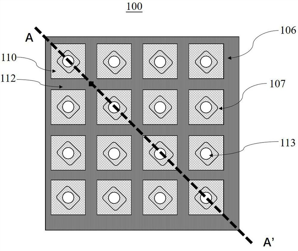
[0082] In some embodiments, the electrode layer 107 is made of a transparent material, such as a transparent conductive film, as the ohmic contact layer and the light outlet of the LED unit 109 .

[0083] In some embodiments, in order to improve the collimation of the light output, a Bragg reflector 108 can also be deposited at the light output port, see Figure 19 , the Bragg reflector 108 is located on the electrode layer 107, and the reflectivity of the Bragg reflector 108 is between 50%-70%; The reflectivity of the mirror 108 is smaller than that of the reflective metal at the bottom of the LED unit 109 .

[0084] In some embodiments, the entire surface of the Bragg mirror 108 is coated on the electrode layer 107 .

[0085] In some embodiments, when the electrode layer 107 is coated on the entire surface of the LED unit 109, and the Bragg reflector 108 is coated on the entire surface of the electrode layer 107, the electrode layer 107 and the Bragg reflector 108 are made ...


PUM

PropertyMeasurementUnit
sizeaaaaaaaaaa
reflectanceaaaaaaaaaa

Abstract

The invention discloses a Micro LED display device and a preparation method, and belongs to the technical field of Micro-LED manufacturing. The Micro LED display chip comprises: a driving panel; an LED unit individually driven by the contacts; the passivation layer is located on the LED unit and comprises a first passivation layer, a second passivation layer and a third passivation layer; and the second reflective layer is formed on the second passivation layer and the third passivation layer. The preparation method comprises the following steps: providing a driving panel, and forming an LED unit on the driving panel; forming a passivation layer on the LED unit; forming a reflective layer on the passivation layer; and stripping the first reflective layer and retaining the second reflective layer. Spontaneous radiation photons are blocked through the reflective layer and are emitted only from the top, crosstalk between adjacent pixels is completely prevented, the photons reflected back by the reflective layer escape from the unique emitting window, and the light emitting power is greatly improved.

Description

technical field [0001] The invention belongs to the technical field of Micro-LED manufacturing, and in particular relates to a Micro-LED display device and a preparation method. Background technique [0002] Micro LED is used in the micro-display industry (such as AR / VR, etc.), because the pixel pitch is very small, which will cause the problem of crosstalk, that is, when a pixel emits light, part of it will leak to adjacent pixels, resulting in Color purity is reduced. At present, there are some technologies, such as resonant cavity technology, which can alleviate the problem of crosstalk to a certain extent, but because Micro LED emits light spontaneously, not stimulated radiation like lasers, some light will still leak from the side wall, causing crosstalk The problem. Contents of the invention [0003] Purpose of the invention: The purpose of the present invention is to provide a Micro LED display device, by setting a reflective layer on the side wall of the LED unit...

Claims


Application Information

Patent Timeline
Patent Type & Authority Applications(China)
IPC IPC(8): H01L25/16H01L21/50H01L27/16H01L33/44H01L33/46H10N19/00
CPCH01L25/167H01L25/50H01L27/156H01L33/44H01L33/46
Inventor 胡双元庄永漳
Owner RAYSOLVE OPTOELECTRONICS (SUZHOU) CO LTD
Learn More