Battery detection device of new energy automobile
A new energy vehicle and battery detection technology, applied in the direction of measuring devices, measuring electricity, measuring electrical variables, etc., can solve the problems of measurement data deviation and prone to safety accidents
Pending Publication Date: 2022-06-21
深圳安博检测股份有限公司
View PDF0 Cites 1 Cited by
- Summary
- Abstract
- Description
- Claims
- Application Information
AI Technical Summary
Problems solved by technology
[0006] (1) The technical problem to be solved by the present invention is: Manually connect wires to the positive and negative poles of the battery, which is prone to safety accidents; Data detection, resulting in a large deviation between the measured data and the actual use data
Method used
View moreImage
Smart ImageViewing Examples
Examples
Embodiment 1
Embodiment 2
Embodiment 3
Login to View More PUM
 Abstract
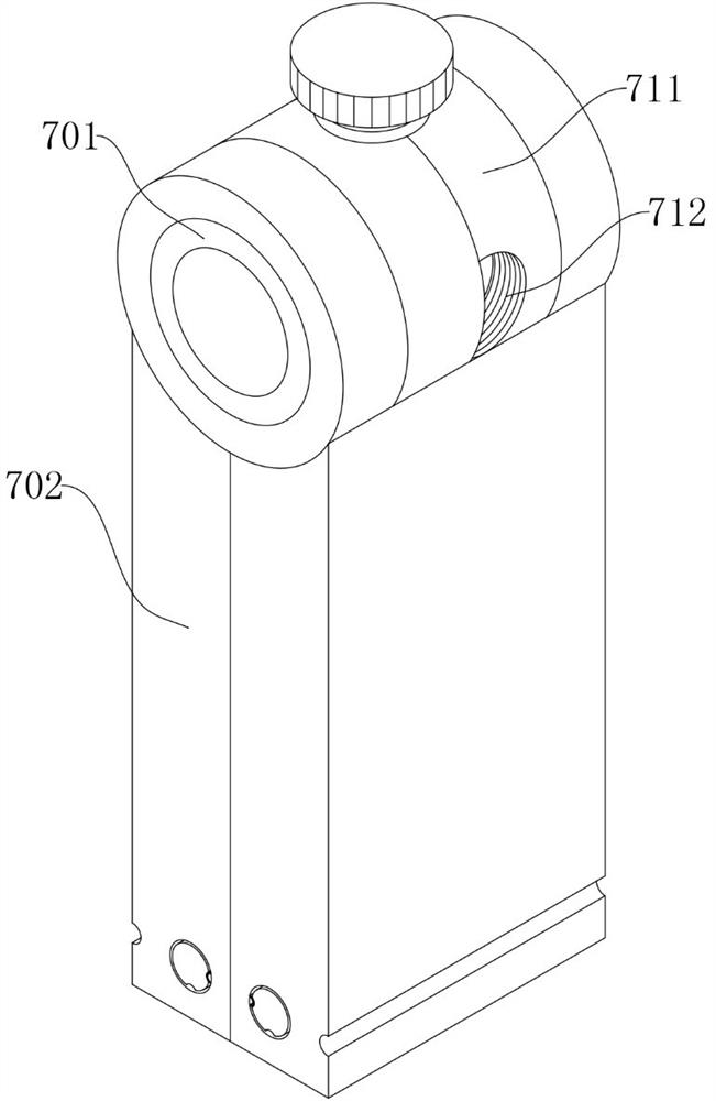
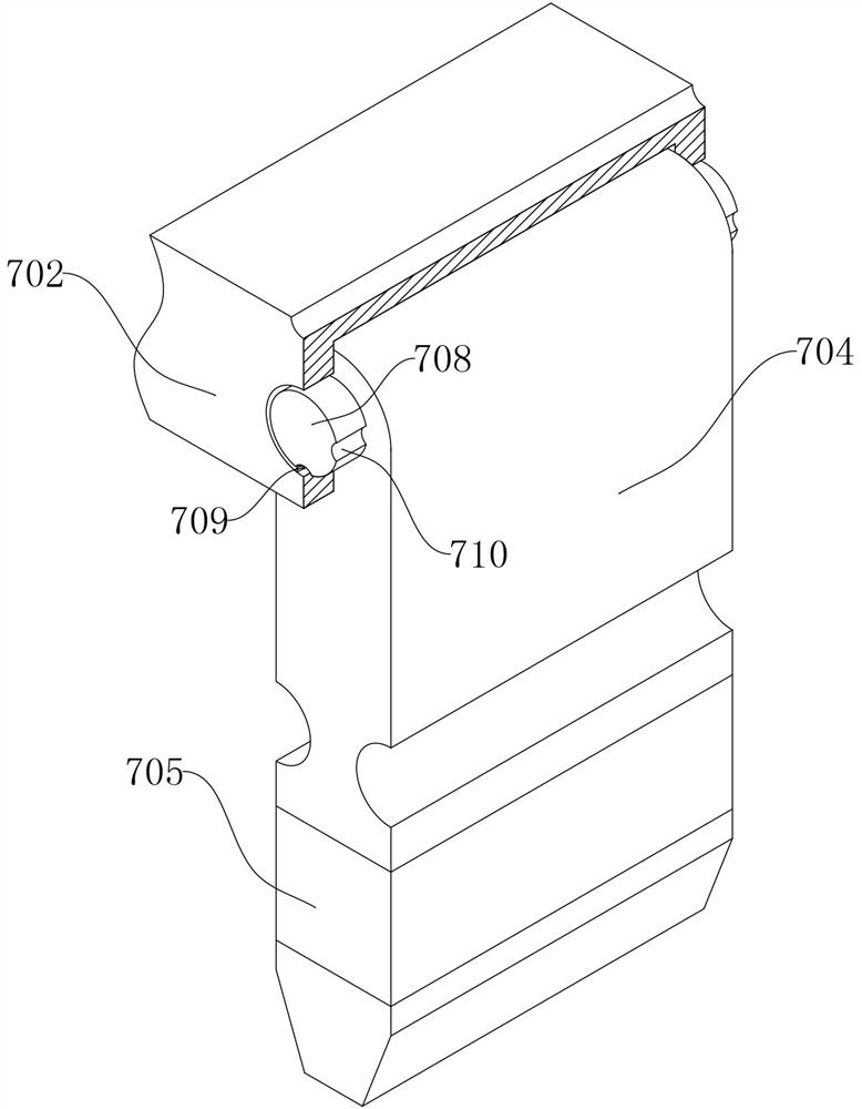
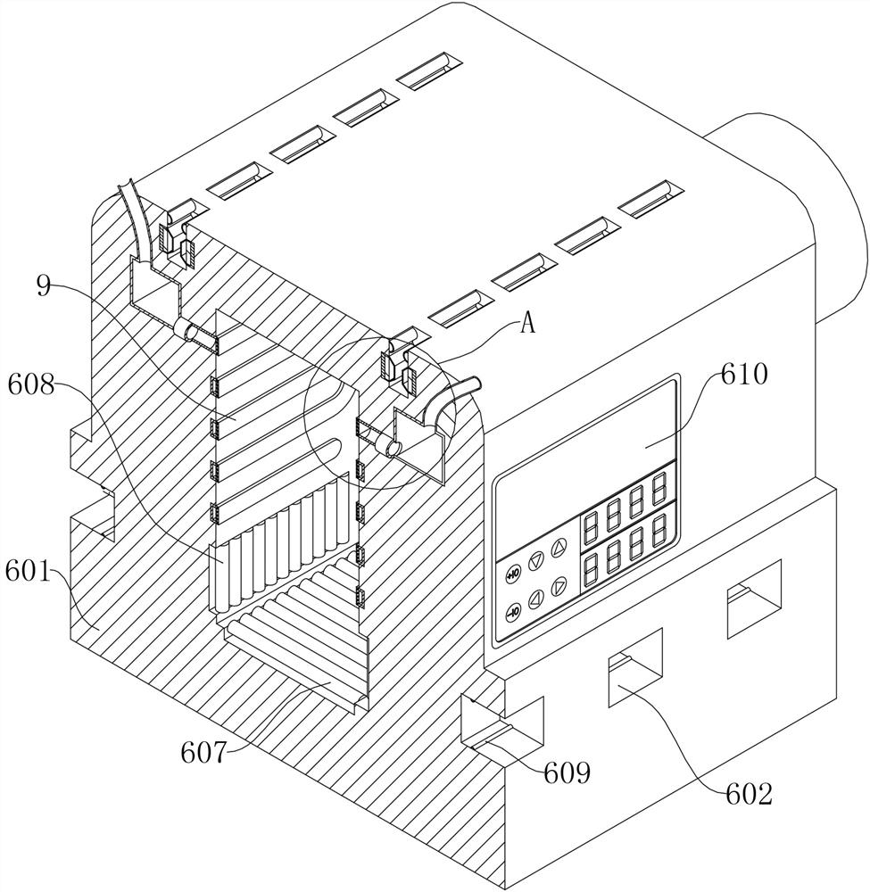
The invention relates to a battery detection device for a new energy automobile, and belongs to the field of electrical performance testing. Through arrangement of a lifting assembly and a self-locking assembly, after a fixed rotating mechanism fixes a battery, an installation connecting mechanism can be deformed and then inserted into two connecting grooves for charging or discharging, so that a third telescopic rod is electrified, and the battery is fixed through the self-locking assembly; when the positive electrode and the negative electrode of the battery make contact with a conductive head, a sliding rod is pushed upwards, connecting rods hinged to the periphery of the sliding rod are squeezed by wedge-shaped grooves, four locking blocks are folded towards the positive electrode and the negative electrode of the battery, the locking blocks clamp the positive electrode and the negative electrode of the battery, and a first L-shaped rod enters along the bevel edge of the bottom end of a first special-shaped groove; the four locking blocks can continuously clamp the positive electrode and the negative electrode of the battery by fixing the position of the sliding rod, and then the electrical performance test of the charging and discharging of the battery is realized through the electrical performance tester, so that the problem that safety accidents are easy to occur due to the fact that the positive electrode and the negative electrode of the battery are manually connected with electric wires is solved.
Description
technical field [0001] The invention relates to a battery detection device for a new energy vehicle, which belongs to the field of electrical performance testing. Background technique [0002] The battery is the power source that provides the power source for new energy vehicles. It mostly refers to the battery that provides power for electric vehicles, electric trains, electric bicycles, and golf carts. It is mainly different from the starting battery used for starting the car engine, and mostly uses valve seal Type lead-acid batteries, open-type tubular lead-acid batteries and lithium iron phosphate batteries. Lithium-iron batteries are new green high-energy chemical power sources that were introduced after 2000 and have been successfully marketed. The electronic equipment and electric toys of the power supply have shown very superior performance. When the discharge current is above the medium level, the discharge time of the lithium-iron battery can reach about 6 times th...
Claims
Login to View More Application Information
Patent Timeline
 Patent Type & Authority Applications(China)
IPC IPC(8): G01R31/388G01R31/389G01R31/392G01R31/396G01R31/36
CPCG01R31/388G01R31/389G01R31/392G01R31/396G01R31/3644
Inventor 朱骥朱骏陈涛
Owner 深圳安博检测股份有限公司
- R&D Engineer
- R&D Manager
- IP Professional
- Industry Leading Data Capabilities
- Powerful AI technology
- Patent DNA Extraction
Learn More Browse by: Latest US Patents, China's latest patents, Technical Efficacy Thesaurus, Application Domain, Technology Topic, Popular Technical Reports.
© 2024 PatSnap. All rights reserved.Legal|Privacy policy|Modern Slavery Act Transparency Statement|Sitemap|About US| Contact US: help@patsnap.com


