
Dielectric waveguide

A technology of dielectric waveguide and dielectric, applied in the direction of waveguide, waveguide-type devices, electrical components, etc., can solve problems such as manufacturing difficulties and strength

Inactive Publication Date: 2004-04-14
MURATA MFG CO LTD
View PDF0 Cites 0 Cited by
  • Summary
  • Abstract
  • Description
  • Claims
  • Application Information

AI Technical Summary

Problems solved by technology

This brings manufacturing difficulties and strength problems

Method used


Image

  • Dielectric waveguide
  • Dielectric waveguide
  • Dielectric waveguide

Examples


Embodiment Construction

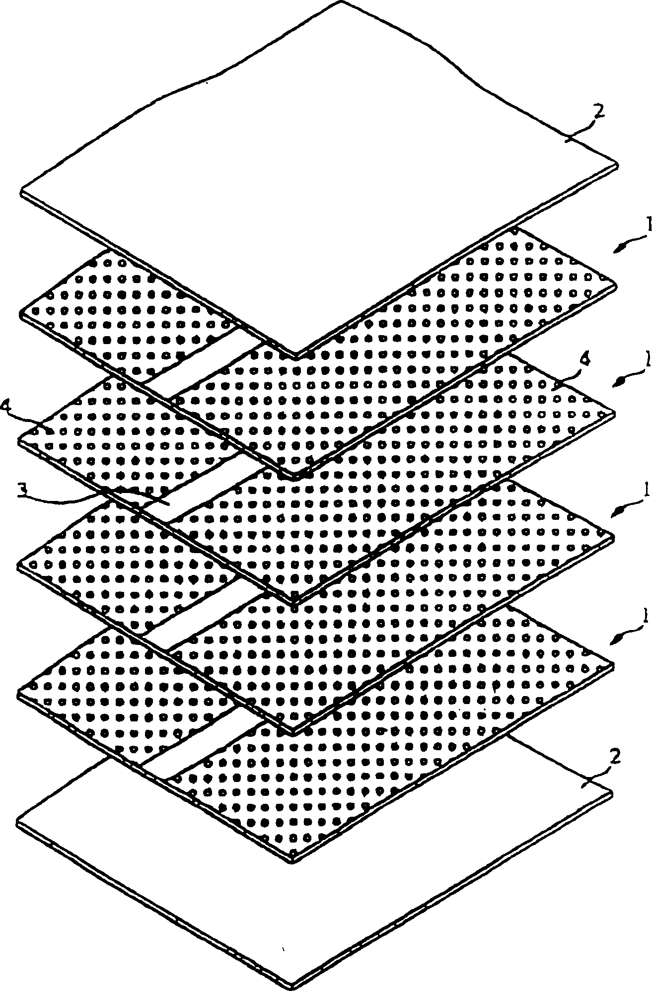
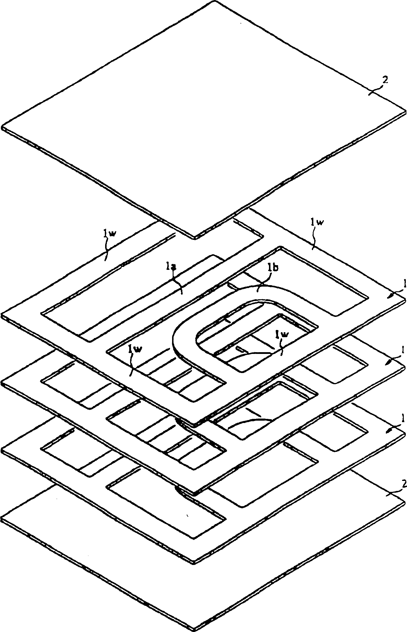
[0032] figure 1 is an exploded perspective view showing each of the dielectric ceramic sheets constituting the dielectric waveguide. The dielectric ceramic sheet 2 serving as the outermost layer has a uniform dielectric constant, and the dielectric ceramic sheet 1 includes a portion 3 with a high dielectric constant and a portion 4 with a low dielectric constant. The low dielectric constant portion 4 is prepared by punching many small holes in a dielectric ceramic sheet. In other words, the effective dielectric constant of the high dielectric constant portion 3 is the same as that of the original dielectric ceramic sheet. The effective dielectric constant of the low dielectric constant portion 4 is lower than that of the high dielectric constant portion 3 .

[0033] Of course, connecting two different dielectric materials can create a dielectric constant difference.

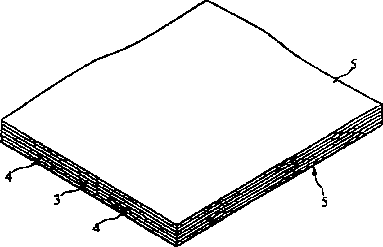
[0034] figure 2 shows that in the untreated flake state (green state) the figure 1 Shown is the case w...


PUM


Abstract

A dielectric waveguide has a plurality of dielectric ceramic sheets each having a high-dielectric-constant portion and a low-dielectric-constant portion. The dielectric ceramic sheets are laminated and baked and electrode films are formed on the outer surfaces thereof. Thus, a dielectric waveguide is obtained in which the high-dielectric-constant portion serves as a propagating area and the low-dielectric-constant portion serves as a non-propagating area.

Description

technical field [0001] The invention relates to a dielectric waveguide, in particular to a transmission line in the millimeter wave frequency band and a microwave frequency band and a dielectric waveguide used in an integrated circuit. Background technique [0002] There is a dielectric waveguide that transmits electromagnetic waves along a dielectric stripline disposed between two parallel conducting planes. A non-radiating dielectric waveguide ("NRD waveguide") is prepared which does not radiate electromagnetic waves from the dielectric stripline, especially when the distance between two conductive planes is half the wavelength or less, providing a non-propagating region. Such transmission lines have been developed as low-loss transmission lines or integrated dielectric waveguide devices. [0003] Figure 15A with 15B Cross-sectional views showing two structures of a conventional NRD waveguide. In FIG. 15(A), the conductive plate 12 is made of metal plates which form tw...

Claims


Application Information

Patent Timeline
Patent Type & Authority Patents(China)
IPC IPC(8): H01P3/16H01P5/02H01P5/18
CPCH01P3/165H01P3/082H01P3/18H01P5/184
Inventor 石川容平谷崎透西田浩齐藤笃
Owner MURATA MFG CO LTD
Learn More