
Dual-frequency microstrip quasi-yagi antenna based on split-ring resonators

A split resonant ring and quasi-yagi technology, which is applied in the direction of loop antennas, antennas, antenna grounding devices, etc., can solve the problems of large size and structure

Pending Publication Date: 2022-06-07
UNIV OF ELECTRONICS SCI & TECH OF CHINA
View PDF0 Cites 0 Cited by
  • Summary
  • Abstract
  • Description
  • Claims
  • Application Information

AI Technical Summary

Problems solved by technology

After the frequency is further increased, the metal rod of the ordinary Yagi antenna forms a three-dimensional structure, which is relatively large for the microwave band.

Method used


Image

  • Dual-frequency microstrip quasi-yagi antenna based on split-ring resonators
  • Dual-frequency microstrip quasi-yagi antenna based on split-ring resonators
  • Dual-frequency microstrip quasi-yagi antenna based on split-ring resonators

Examples


Embodiment Construction

[0026] The specific embodiments of the present invention are described below with reference to the accompanying drawings, so that those skilled in the art can better understand the present invention. It should be noted that, in the following description, when the detailed description of known functions and designs may dilute the main content of the present invention, these descriptions will be omitted here.

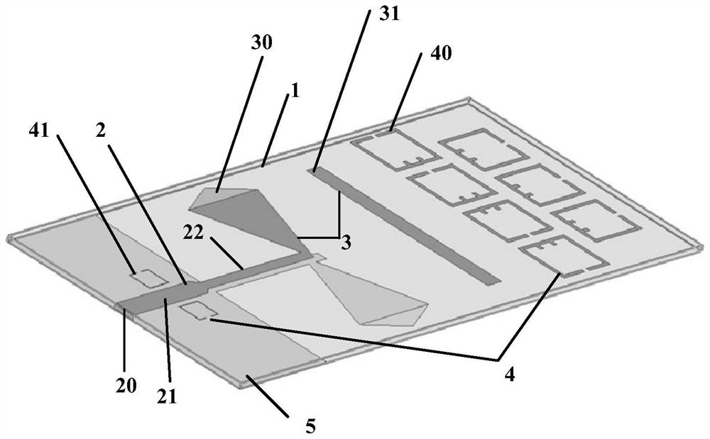
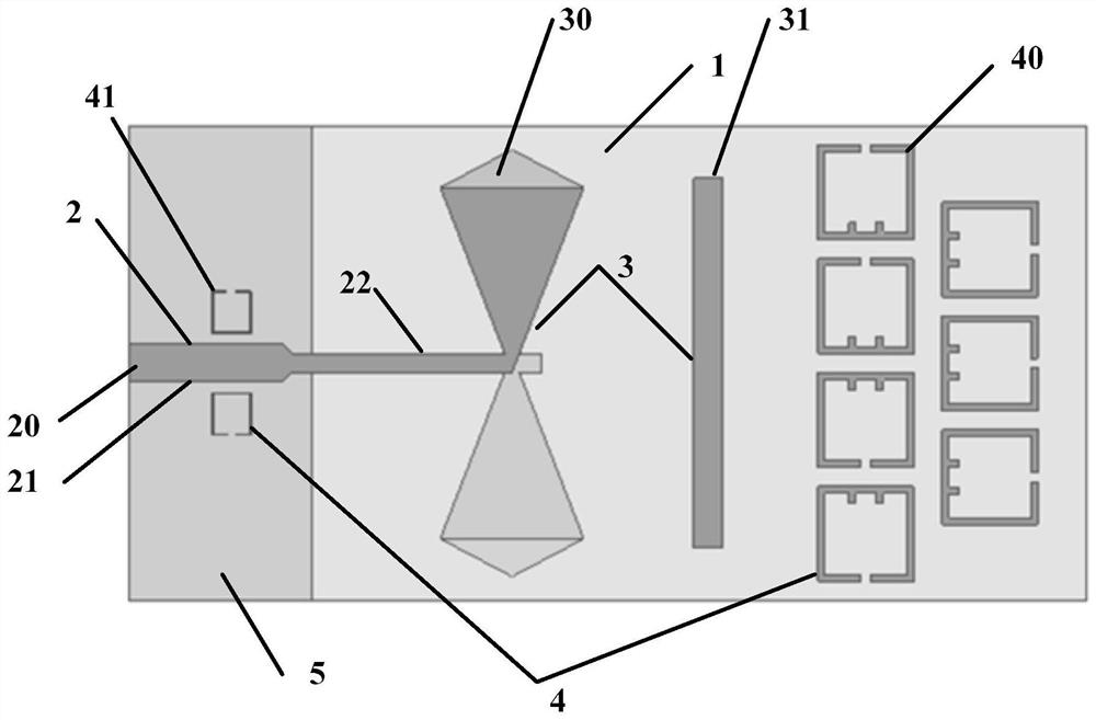
[0027] figure 1 It is a schematic structural diagram of a specific embodiment of the dual-frequency microstrip quasi-Yagi antenna based on the split resonant ring of the present invention, figure 2 Yes figure 1 The schematic diagram of the planar structure of the dual-frequency microstrip quasi-Yagi antenna based on the split resonator is shown.

[0028] In this embodiment, as figure 1 , 2 As shown, the dual-frequency microstrip quasi-Yagi antenna based on the split resonant ring of the present invention includes a dielectric substrate 1, a feeding network 2, a quasi...


PUM


Abstract

The invention discloses a dual-frequency micro-strip quasi-yagi antenna based on split-ring resonators, which is characterized in that two rows of low-frequency resonant rings playing a role in energy gathering of a director are improved: four split-ring resonators with side openings in one row close to the director side are subjected to magnetic field coupling; inductance in the split-ring resonator equivalent circuit can be increased through the inner side protrusions, and coupled magnetic field energy is increased if the inductance is increased. After the first coupling, most energy is converged at the interval between every two split-ring resonators, three split-ring resonators with openings on the right sides are arranged in a row far away from the director side and are placed on the right side of the interval, the coupling of an electric field and a magnetic field is carried out through stepped arrangement, and the energy is converged in the longitudinal direction of the antenna again, so that the field angle of a main lobe is smaller, and the antenna is more compact. Therefore, the gain is increased to 7. Besides, the high-frequency split-ring resonators on the upper side and the lower side of the microstrip feeder enable energy transmitted by the input port to be coupled by the high-frequency split-ring resonators in an electromagnetic coupling mode, and electromagnetic energy can generate different high frequencies to be emitted into a free space, so that dual-frequency work of the antenna is realized.

Description

technical field [0001] The invention belongs to the technical field of antennas, and more particularly, relates to a dual-frequency microstrip quasi-Yagi antenna based on a split resonant ring. Background technique [0002] Yagi-Uda antennas have excellent gain and directivity, and have a simple structure that is easy to implement and install. After the frequency is further increased, the ordinary Yagi antenna forms a three-dimensional structure through a metal rod, which is larger for the microwave band. The microstrip quasi-Yagi antenna replaces each part of the Yagi antenna equivalently by the microstrip line, and radiates the antenna through the lower loss dielectric substrate, so that the structure of the microstrip quasi-Yagi antenna is more compact, the frequency is higher, and it has the advantages of miniaturization, low power consumption The unique advantages of profile, light weight, small size, and easy conformality also have the advantages of high gain and good...

Claims


Application Information

Patent Timeline
Patent Type & Authority Applications(China)
IPC IPC(8): H01Q1/38H01Q1/50H01Q1/48H01Q5/10H01Q5/20H01Q5/42H01Q5/307H01Q7/00H01Q19/30
CPCH01Q1/38H01Q1/50H01Q1/48H01Q5/10H01Q5/20H01Q5/42H01Q5/307H01Q7/00H01Q19/30
Inventor 刘宸宇徐进张宇驰岳玲娜殷海荣蔡金赤赵国庆
Owner UNIV OF ELECTRONICS SCI & TECH OF CHINA
Learn More