
Spare and accessory part anti-collision treatment device for wholesale of spare and accessory parts

A technology for processing devices and spare parts, applied in the directions of external parts and internal parts, etc., can solve problems such as low use efficiency, inability to place a large number of parts, etc., and achieve the effect of preventing falling

Pending Publication Date: 2022-06-07
广州天奕贸易有限公司
View PDF1 Cites 0 Cited by
  • Summary
  • Abstract
  • Description
  • Claims
  • Application Information

AI Technical Summary

Problems solved by technology

[0005] In order to overcome the disadvantages that the anti-collision storage box for shaft parts cannot store a large number of spare parts and the use efficiency is low, the technical problem of the present invention is to provide a spare parts wholesaler that can store a large number of spare parts and has high use efficiency. Accessories anti-collision processing device

Method used


Image

  • Spare and accessory part anti-collision treatment device for wholesale of spare and accessory parts
  • Spare and accessory part anti-collision treatment device for wholesale of spare and accessory parts
  • Spare and accessory part anti-collision treatment device for wholesale of spare and accessory parts

Examples


Embodiment 1

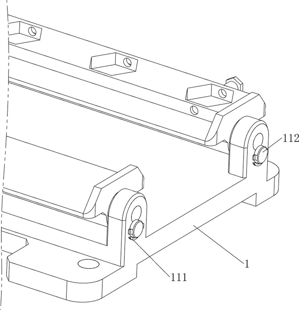
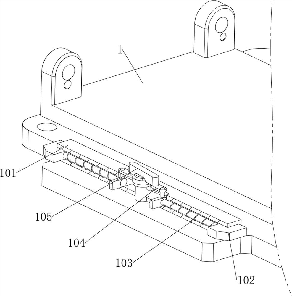
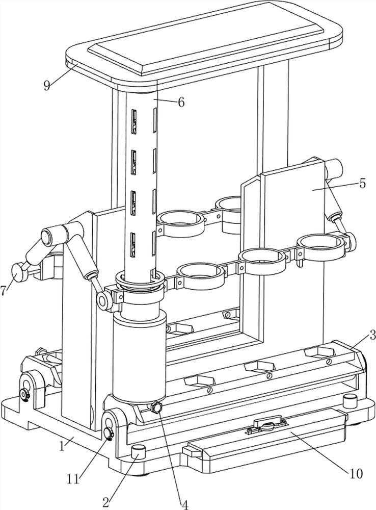
[0034] An anti-collision processing device for spare parts for wholesale of spare parts, such as Figure 1-6 As shown, it includes a base 1, a suction cup 2, a turret 3, a first fixing bolt 4, a first connecting plate 5, a support mechanism 6 and a rotating mechanism 7. The four corners of the upper side of the base 1 are provided with suction cups 2, and the suction cups 2 The stability of the device can be improved. The left and right sides of the upper part of the base 1 are rotatably connected with a turret 3. The turret 3 is convenient for people to take out and place the spare parts. The front side of the right part of the turret 3 is provided with a removable first fixing bolt. 4. There is a first connecting plate 5 in the middle of the upper side of the base 1. The first connecting plate 5 can separate the left turret 3 and the right turret 3 to prevent the placed parts from colliding, and the right turret 3 The front side is provided with a support mechanism 6, which ...

Embodiment 2

[0039] On the basis of Example 1, as Figure 7 , Figure 8 and figure 2 As shown, it also includes an unfolding mechanism 8 capable of unfolding and storing spare parts. The unfolding mechanism 8 includes a second fixing rod 81, a second sliding tube 82, a first connecting rod 83, a second fixing bolt 84, a first fixing rod The block 85, the first rotating rod 86, the torsion spring 87 and the second connecting rod 88, a second fixing rod 81 is provided in the middle of the inner top wall of the first sliding tube 62, and a second sliding tube 82 is provided in the middle of the upper side of the bearing plate 64, Three second sliding pipes 82 are slidably connected to the second fixing rod 81 , and four second fixing bolts 84 are arranged on the upper side of the second sliding pipes 82 along the circumferential direction. The connecting rod 83 and the second fixing rod 81 are evenly provided with four first fixing blocks 85 , and the first fixing blocks 85 are rotatably c...


PUM


Abstract

The invention relates to a part anti-collision treatment device, in particular to a part anti-collision treatment device for part wholesale. According to the technical aims, the anti-collision processing device for the spare and accessory parts for wholesale can contain a large number of spare and accessory parts and is high in use efficiency. A part anti-collision processing device for part wholesale comprises a base, suction cups, rotating frames and the like, the suction cups are arranged at the four corners of the upper side of the base, and the rotating frames are rotationally arranged on the left side and the right side of the upper portion of the base. According to the device, the device is adsorbed to a plane through a suction cup, then an electric push rod is started, so that a first connecting plate and a clamping plate move towards the outer side, then a first sliding pipe and a connecting pipe are fixed to a rotating frame, then parts are sequentially placed on the first sliding pipe, and in this way, a large number of parts can be placed in order.

Description

technical field [0001] The invention relates to an anti-collision processing device for spare parts, in particular to an anti-collision processing device for spare parts for wholesale of spare parts. Background technique [0002] Spare parts refer to products that have been completed and constitute an integral part of the user's product, such as integrated circuit blocks, meters, instruments, etc., the spare parts will collide during the placement process, which will cause damage to the spare parts. [0003] The patent application number is CN201921764494.5 An anti-collision placement box for shaft parts includes a box body, a fixing plate is slidably connected to the inside of the box body, and a first fixing block is fixedly connected to the top of the fixing plate, and the first fixing block is A first placement slot is opened on the top of the first fixing block, a first baffle is fixedly connected to both sides of the top of the first fixing block, a supporting plate is...

Claims


Application Information

Patent Timeline
IPC IPC(8): B65D25/24B65D25/10
CPCB65D25/24B65D25/10
Inventor 余晓晴
Owner 广州天奕贸易有限公司
Learn More