
Non-magnetic bearing steel ball machining process

A processing technology, magnetic bearing technology, applied in the field of non-magnetic bearing steel ball processing technology, to achieve the effect of ensuring stability, quality assurance, and stable quality level

Active Publication Date: 2022-06-07
温州市中特钢球有限公司
View PDF4 Cites 0 Cited by
  • Summary
  • Abstract
  • Description
  • Claims
  • Application Information

AI Technical Summary

Problems solved by technology

[0002] In today's large-scale research and development of high-precision weapons, the requirements for the positioning accuracy of missiles and supersonic weapons are getting higher and higher. The influence of the earth's magnetic field has a negative impact on precise positioning. In order to overcome the influence of geomagnetism, beryllium bronze balls were originally used to make beryllium Bronze bearings, but there are two problems. First, beryllium bronze is poisonous, and poisonous gas will be produced during processing. Second, its hardness is only more than HRc30, and its service life is not long. Because of its low hardness, the accuracy of steel balls cannot be improved.
For this reason, our country has developed a new material, which is the non-magnetic bearing steel developed and produced by Chongqing Iron and Steel Research Institute (the grade is 0Cr40Ni55Al3, code-named G60). This material has good stability, high strength, and a hardness of HRC56 after heat treatment. The disadvantage is the material cost. Very high (about 1500 yuan / kg) the toughness is too high and the processing is very difficult

Method used


Image

  • Non-magnetic bearing steel ball machining process
  • Non-magnetic bearing steel ball machining process
  • Non-magnetic bearing steel ball machining process

Examples


Embodiment Construction

[0025] The technical solutions in the embodiments of the present invention will be clearly and completely described below with reference to the accompanying drawings in the embodiments of the present invention. Obviously, the described embodiments are only a part of the embodiments of the present invention, but not all of the embodiments. Based on the embodiments of the present invention, all other embodiments obtained by those of ordinary skill in the art without creative efforts shall fall within the protection scope of the present invention.

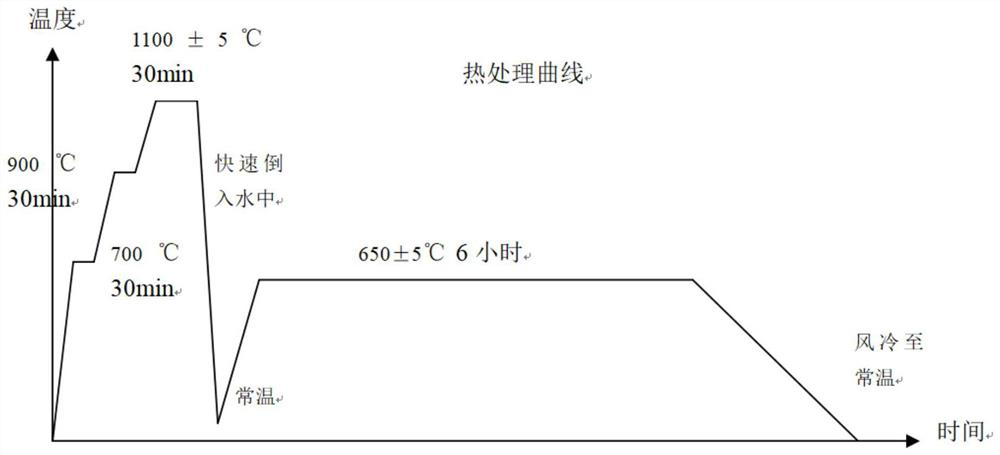
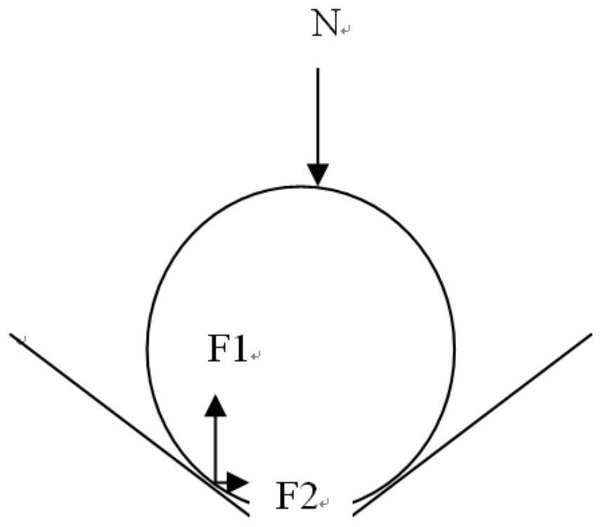
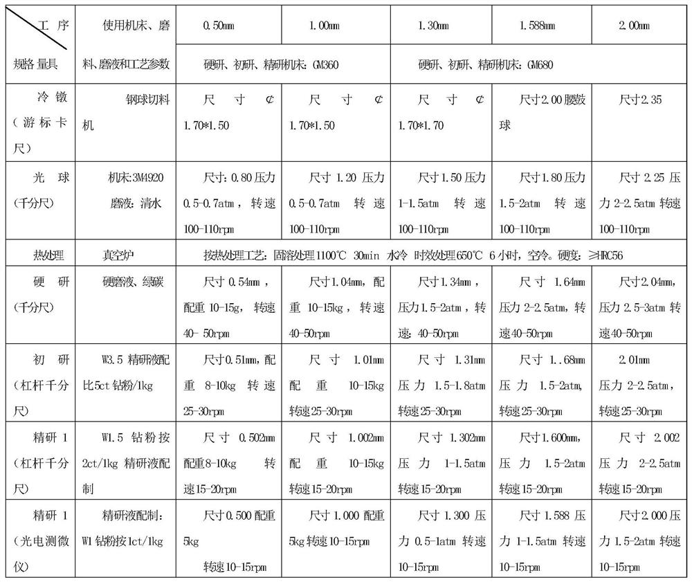
[0026] The following will be attached in conjunction with the manual figure 1 , 2 The present invention is further described.

[0027] The present invention adopts following technical scheme:

[0028] The raw material is filamentous with a diameter of about 1.70mm, but due to its high toughness, the drawn wire is of irregular shape, so drawing is not used. The whole process flow is as follows:

[0029] Raw material inspection (rem...


PUM

PropertyMeasurementUnit
hardnessaaaaaaaaaa

Abstract

The invention discloses a non-magnetic bearing steel ball machining technology. The technology comprises the following steps of raw material inspection, material cutting (cold heading), ball polishing, cleaning, heat treatment, cleaning, ball sorting and picking, first hard grinding, second hard grinding, primary grinding, first fine grinding, second fine grinding, cleaning, rust prevention, ball picking and inspection and packaging. According to the machining process, existing equipment is fully utilized, products which are small, made of special materials and used for special purposes are machined, the quality level is stable, and the requirements of the national defense industry are fully met; a millstone machining mode with a large groove angle, a large groove distance, small groove depth and a middle opening is adopted, so that the stability and the consistency in the machining process of the extra-small steel balls are ensured, and unqualified products are prevented from being produced; and novel grinding materials and grinding liquid are adopted, so that the stability and efficiency of the process are ensured, the quality of finished products is ensured, and the device is more environment-friendly.

Description

technical field [0001] The invention relates to bearings used in directional gyroscopes such as missiles and satellites and avionics in the military industry, in particular to the processing technology of non-magnetic bearing steel balls. Background technique [0002] In today's large-scale research and development of high-precision weapons, the requirements for the positioning accuracy of missiles and supersonic weapons are getting higher and higher. The influence of the earth's magnetic field has an adverse effect on precise positioning. In order to overcome the influence of geomagnetism, beryllium bronze balls were originally used to make beryllium Bronze bearings, but there are two problems. First, beryllium bronze is poisonous and will produce poisonous gas during processing. Second, its hardness is only more than HRc30, and its service life is not long. Due to its low hardness, the accuracy of steel balls cannot be improved. To this end, my country has developed a new ...

Claims


Application Information

Patent Timeline
Patent Type & Authority Applications(China)
IPC IPC(8): B23P15/00
CPCB23P15/00Y02P10/20
Inventor 林钟杰张红路
Owner 温州市中特钢球有限公司
Learn More