
Centrifugal impeller for blood pump and blood pump

A technology of centrifugal impeller and centrifugal blade, applied in the field of centrifugal impeller for blood pump and blood pump, can solve the problems of rotor instability, blood accumulation, and reduction of hydraulic performance of blood pump, so as to increase structural strength and stability, and avoid thrombosis. The effect of forming and increasing blood flow

Pending Publication Date: 2022-06-07
BEIHANG UNIV
View PDF0 Cites 0 Cited by
  • Summary
  • Abstract
  • Description
  • Claims
  • Application Information

AI Technical Summary

Problems solved by technology

Above the center of the centrifugal impeller is usually the place where the main flow and the secondary flow collide, often resulting in a large energy loss and high non-physiological shear force, which will also lead to a decrease in the hydraulic performance of the blood pump
In addition, below the center of the centrifugal impeller, near the secondary flow channel, the blood flow rate is slow, making blood easily stagnant in the secondary flow channel area
The existence of non-physiological high shear force will inevitably cause damage to blood cells and proteins (such as destroying red blood cells and activating platelets, etc.), while the existence of stagnant flow areas will lead to blood stasis, which will further lead to the formation of thrombus
What's more serious is that once a thrombus occurs at the bearing, it is easy to destroy the dynamic balance, resulting in the instability of the rotor, which in turn leads to the failure of the blood pump, which may lead to serious clinical accidents

Method used


Image

  • Centrifugal impeller for blood pump and blood pump
  • Centrifugal impeller for blood pump and blood pump
  • Centrifugal impeller for blood pump and blood pump

Examples


Embodiment Construction

[0036] In order to make the objectives, technical solutions and advantages of the present invention clearer, the present invention will be further described in detail below with reference to the specific embodiments and the accompanying drawings. It should be understood that these descriptions are exemplary only and are not intended to limit the scope of the invention. Also, in the following description, descriptions of well-known structures and techniques are omitted to avoid unnecessarily obscuring the concepts of the present invention.

[0037] A schematic diagram of an embodiment according to the invention is shown in the accompanying drawing. The figures are not to scale and some details may have been omitted for clarity. The various regions shown in the figures and their relative sizes and positional relationships are only exemplary, and may vary in practice due to manufacturing tolerances or technical limitations, and those skilled in the art can make additional change...


PUM


Abstract

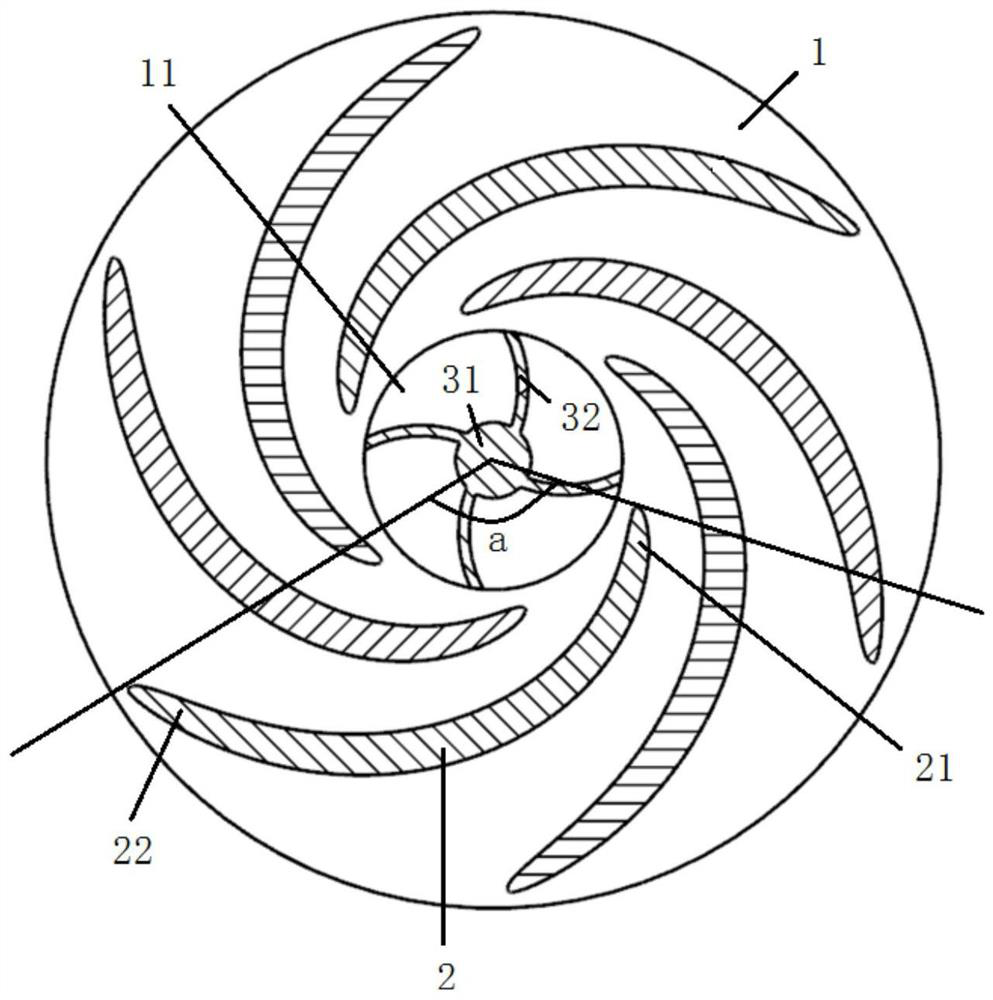
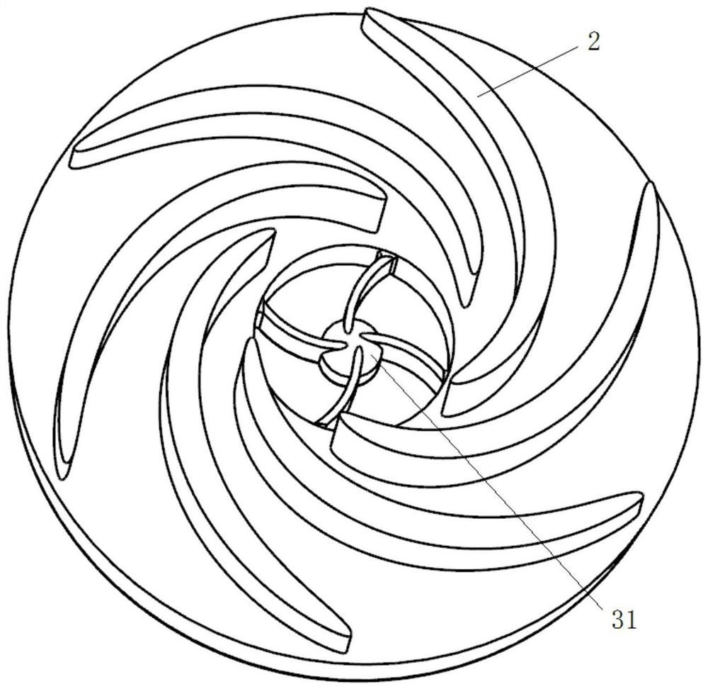
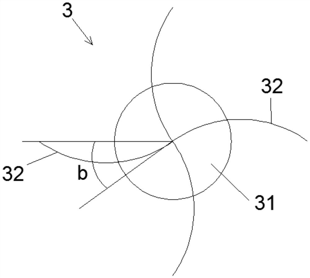
The invention discloses a centrifugal impeller for a blood pump and the blood pump. The centrifugal impeller for the blood pump comprises a round bottom plate, and a through hole is formed in the middle of the bottom plate to form a secondary flow channel; the centrifugal blades are arranged on the upper surface of the bottom plate, each centrifugal blade is a banana-shaped blade with a thick middle part and two thin ends, the wrap angle of each centrifugal blade is greater than or equal to 90 degrees, and the centrifugal blades radially extend from the outer edge of the through hole to the periphery of the bottom plate. The supporting structure comprises a supporting shaft and a supporting blade, the supporting shaft is arranged in the center of the through hole, one end of the supporting blade is connected with the supporting shaft, and the other end of the supporting blade is connected with the bottom plate. According to the banana-shaped blade structure with the wrap angle larger than or equal to 90 degrees, blood damage and thrombus in the impeller can be reduced. The supporting structure is arranged in the through hole of the bottom plate and can support the centrifugal impeller to rotate at a high speed, the overall structural strength and stability are improved, the flow speed of blood in the secondary flow channel can be increased by arranging the supporting blades, thrombus is avoided, and the dynamic balance of the rotor is improved.

Description

technical field [0001] The invention relates to the technical field of rotors, in particular to a centrifugal impeller for a blood pump and a blood pump. Background technique [0002] A blood pump is a medical device that can assist human blood circulation, and is often used for extracorporeal circulation support and heart failure treatment. The blood pump is also an important component of the extracorporeal membrane oxygenation (Extracorporeal Membrane Oxygenation, ECMO) system. At present, the commonly used blood pump in clinical practice is the magnetic coupling driven blood pump. The magnetic coupling driving motor outside the pump head drives the centrifugal impeller inside the pump head to rotate to promote blood circulation. The high-speed rotation of the impeller of a centrifugal blood pump results in the appearance of turbulent flow in the impeller. The presence of these turbulences, on the one hand, affects the flow and reduces the hydraulic performance of the bl...

Claims


Application Information

Patent Timeline
IPC IPC(8): A61M60/113A61M60/232A61M60/216A61M60/38A61M60/419A61M60/804A61M60/806A61M60/845
CPCA61M60/113A61M60/232A61M60/216A61M60/38A61M60/419A61M60/804A61M60/806A61M60/845A61M60/825A61M60/109
Inventor 陈增胜李远樊瑜波邓小燕
Owner BEIHANG UNIV
Learn More