
Indirect evaporative cooling heat dissipation system of data center

An evaporative cooling and heat dissipation system technology, applied in natural cooling systems, cooling/ventilation/heating renovation, air conditioning systems, etc., can solve the problems of server performance reduction, server pollution, high power consumption in four seasons, energy efficiency improvement, etc.

Pending Publication Date: 2022-06-03
SHENZHEN ESIN TECH CO LTD
View PDF0 Cites 0 Cited by
  • Summary
  • Abstract
  • Description
  • Claims
  • Application Information

AI Technical Summary

Problems solved by technology

[0002] Traditional data centers usually use chilled water circulation and mechanical refrigeration to dissipate heat in the data center. This method consumes a lot of power in four seasons and encounters bottlenecks in energy efficiency improvement. Currently, natural cooling includes direct fresh air cooling and indirect evaporative cooling. Due to the dust and impurities mixed in the fresh air, direct fresh air cooling can cause great pollution to the server for a long time, resulting in a decrease in server performance. However, the current mainstream indirect evaporative cooling equipment cannot meet the cooling needs of the data center throughout the year, and mechanical refrigeration is still required in summer. auxiliary; but theoretically speaking, with the gradual maturity of the application of indirect evaporative cooling technology, in some low-temperature and dry northern regions such as Northwest China and Inner Mongolia, the data center can meet the annual cooling demand only by using indirect evaporative cooling; the present invention is Research on improving the efficiency of indirect evaporative cooling to achieve year-round free cooling

Method used


Image

  • Indirect evaporative cooling heat dissipation system of data center
  • Indirect evaporative cooling heat dissipation system of data center
  • Indirect evaporative cooling heat dissipation system of data center

Examples


Embodiment Construction

[0026] To facilitate the understanding of the present invention, the present invention will be described more comprehensively below with reference to the relevant drawings. Preferred embodiments of the present invention are given in the accompanying drawings. However, the present invention may be implemented in many different forms, and is not limited to the embodiments described herein. Instead, the object of providing these embodiments is to make the understanding of the disclosures of the present invention more thorough and comprehensive.

[0027] To be clear, when a component is said to be "fixed" to another component, it can be directly on another component or it can also be present in the center. When one component is considered to be "connected" to another component, it can be directly connected to another component or may also have a centering component.

[0028]Unless otherwise defined, all technical and scientific terms used herein and those skilled in the technical art ...


PUM


Abstract

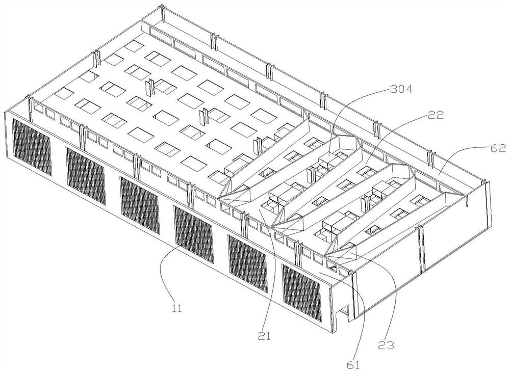
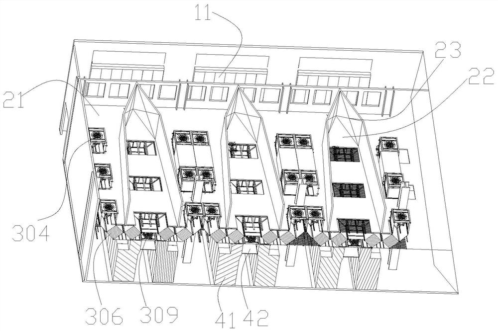
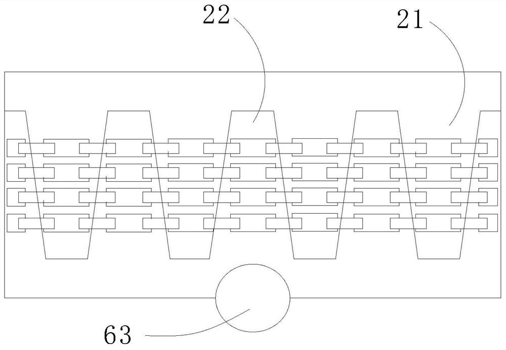
The invention relates to a data center indirect evaporation cooling heat dissipation system which comprises an air pre-cooling evaporation module, an evaporation cooling heat exchange device, an outer circulation air inlet and outlet conveying unit, a distributed heat channel closed cabinet module and an indirect evaporation water cooling module. The indirect evaporation water cooling module is connected with the air pre-cooling evaporation module through a pipeline, and the evaporation cooling heat exchange device is located between the distributed heat channel closed cabinet module and the outer circulation air inlet and outlet conveying unit; the evaporative cooling efficiency, the heat exchange efficiency and the cold and hot air conveying efficiency are improved from multiple aspects, an outer circulation cold and hot air channel is combined with building design, the building utilization rate is increased, the single-rack building cost is reduced, and the aim of natural cooling all year round in most northern areas can be achieved; hot air generated by the server can be cooled to 18-27 DEG C, and the air supply temperature standard required by the national standard is met.

Description

[0001] The present invention relates to the field of data center evaporative cooling technology, specifically to a fully natural cooling data center indirect evaporative cooling cooling cooling system. Background [0002] Traditional data centers usually use frozen water circulation and mechanical refrigeration to dissipate heat in the data center, which has a large power consumption in all seasons and encounters bottlenecks in energy efficiency improvement; At present, the use of natural cooling has direct fresh air cooling and indirect evaporative cooling, direct fresh air cooling due to the dust impurities contained in the fresh air, a long time can cause great pollution to the server, resulting in reduced server performance, and the current mainstream indirect evaporation cooling equipment can not meet the cooling needs of the data center throughout the year, summer still need mechanical refrigeration assistance; However, in theory, with the gradual maturity of the application ...

Claims


Application Information

Patent Timeline
Patent Type & Authority Applications(China)
IPC IPC(8): H05K7/20F24F5/00F24F6/04F24F13/28
CPCH05K7/20827F24F5/0035F24F6/04F24F13/28Y02B30/54
Inventor 白本通刘和军吕政举
Owner SHENZHEN ESIN TECH CO LTD
Learn More