
An anti-shelling and non-combustible thermal insulation system for aircraft testing

A technology of aircraft testing and thermal insulation system, which is applied in the fields of aircraft component testing, thermal insulation, construction, etc. It can solve the problems of low bonding strength between PIR material and stainless steel, low bonding strength between inner panel and core material, and inability to realize automatic production. Achieve the effect of decomposition and buffering external impact force, facilitating later maintenance and avoiding being damaged

Active Publication Date: 2022-07-22
CHINA AIRPLANT STRENGTH RES INST
View PDF0 Cites 0 Cited by
  • Summary
  • Abstract
  • Description
  • Claims
  • Application Information

AI Technical Summary

Problems solved by technology

[0004] Insulation storage panels are usually composed of inner panels, outer panels, core materials and embedded connectors. Currently, non-combustible insulation storage panels in climate laboratories used for aircraft testing generally have low bonding strength between inner panels and core materials. However, the problem of shelling occurred, resulting in a very low service life of the insulation storage board
The reasons for the shelling of non-combustible thermal insulation panels come from three aspects: First, the core material of non-combustible thermal insulation panels is PIR material, and the bonding strength between this material and the metal panel is higher than that of PUR core materials used in flammable and flame-retardant thermal insulation panels. The bonding strength of the metal panel is low; secondly, although the bonding strength between the PIR material and the metal panel can be improved by increasing the contact pressure between the PIR material and the metal panel during the production process of the thermal insulation storage panel, the pre-embedded method used for the broken cold bridge The connection method is limited, and it cannot realize automatic production; third, the thermal insulation board used in the high and low temperature environmental chamber and climate laboratory, the inner panel is in a harsh environment, and stainless steel is usually used, and the bonding strength of PIR material and stainless steel lower

Method used


Image

  • An anti-shelling and non-combustible thermal insulation system for aircraft testing
  • An anti-shelling and non-combustible thermal insulation system for aircraft testing
  • An anti-shelling and non-combustible thermal insulation system for aircraft testing

Examples


Embodiment 1

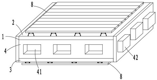
[0039] like figure 1 As shown, an anti-shelling and non-combustible thermal insulation system for aircraft testing is formed by splicing a plurality of thermal insulation storage boards 1. And form the buckle frame 4 of the heat preservation cavity 40, the heat preservation core material 5 and the reinforcing fastener 6 arranged in the heat preservation cavity 40;

[0040] The inner panel 2 is made of stainless steel, and the surface of the inner panel 2 is matte matte;

[0041] like figure 1 , 8 , 11, the front and rear sides of the buckle frame 4 are evenly provided with three first clamping grooves 41, and the left and right sides of the buckle frame 4 are evenly provided with three first clamping projections 42. A seam thermal insulation connecting component 7 is provided between the fastening frames 4 corresponding to each thermal insulation storage board 1;

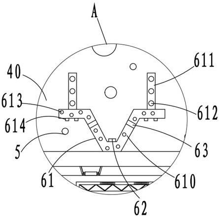
[0042] like figure 2 , 3 As shown in , 6 and 7, the reinforcing fastener 6 includes a first π-shaped embed...

Embodiment 2

[0049] This embodiment differs from Embodiment 1 in that:

[0050] like Figure 9 , 12 As shown, the side wall of the horizontal reinforcement rod 72 located inside the adjustment port 71 is provided with a first engaging tooth 721, the outside of the adjustment port 71 is provided with a horizontal pulling rod 722 along the length direction, and the interior of the adjustment port 71 is provided with a horizontal engaging rod 723 , the horizontal pulling rod 722 and the corresponding horizontal clamping rod 723 are connected by a connecting column 724, three connecting springs 725 are provided between the horizontal clamping rod 723 and the inner wall of the adjustment port 71, and the horizontal clamping rod 723 is provided with a third connecting spring 725. A second engaging tooth 726 engages with one engaging tooth 721 .

Embodiment 3

[0052] This embodiment differs from Embodiment 2 in that:

[0053] like figure 1 , 2 , 4, the inner panel 2 and the outer panel 3 side walls are provided with an anti-collision reinforcing assembly 8, and the anti-collision reinforcing assembly 8 includes 8 rotating buffer rods 80 evenly arranged on the inner panel 2 and the outer panel 3 side walls 80, side There are 10 horizontal anti-collision plates 81 provided with anti-collision installation grooves 810, 4 connecting cylinders 82 disposed on the horizontal anti-collision plate 81 and away from the side of the anti-collision installation groove 810, located in the anti-collision installation groove 810 and connected to the side of the anti-collision installation groove 810. The anti-collision mounting grooves 810 are connected by three buffer springs 830 and the impact buffer plate 83 in the same plane as the horizontal anti-collision plate 81, and the connecting cylinder 82 is in one-to-one correspondence with the rotat...


PUM

PropertyMeasurementUnit
thicknessaaaaaaaaaa
thicknessaaaaaaaaaa
thicknessaaaaaaaaaa

Abstract

The invention provides an anti-shelling and non-combustible heat preservation system for aircraft testing, which belongs to the technical field of aircraft testing. The thermal insulation system is formed by splicing a plurality of thermal insulation storage boards, and the thermal insulation storage board includes an inner panel, an outer panel, a fastening frame for connecting the inner panel and the outer panel and forming a thermal insulation cavity, and a thermal insulation core arranged in the thermal insulation cavity. In the automatic production process, the inner panel can be placed in the lower position of the production line, which significantly improves the bonding strength between the inner panel and the thermal insulation core material. In the inner panel, the insulation core material is reinforced by reinforcing fasteners, which can further increase the bonding strength between the inner panel and the insulation core material, and avoid shelling of the insulation core material.

Description

technical field [0001] The invention belongs to the technical field of aircraft testing, in particular to an anti-shelling and non-combustible thermal insulation system for aircraft testing. Background technique [0002] Aircraft testing refers to subjecting the aircraft to the effects of climatic environmental stress under indoor simulation or outdoor natural climatic conditions, so as to obtain information on the extreme ability of the aircraft to withstand the climatic environment, and adapt to the climatic environment of the aircraft according to the development requirements, failure criteria and test data. Comprehensive evaluation is carried out to determine the degree to which the aircraft's climatic and environmental adaptability meets the requirements. [0003] As a large-scale carrying facility equipped with environmental tests, the climate laboratory can accommodate full-size aircraft and provide all-weather, time-limited high temperature, low temperature, rain, sn...

Claims


Application Information

Patent Timeline
Patent Type & Authority Patents(China)
IPC IPC(8): E04B1/80E04B1/76E04B1/61B64F5/60
CPCE04B1/80E04B1/7604E04B1/6116B64F5/60Y02T50/40
Inventor 曹琦刘海燕任战鹏吴敬涛王博言吴学敏周青松
Owner CHINA AIRPLANT STRENGTH RES INST
Learn More